Chapter 7
Digital I/O
©
National Instruments Corporation
7-9
DAQ-STC Technical Reference Manual
Function
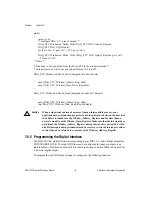
DIO_Pin_Configure
{
DIO_Pins_Dir = [ijklmnop];
}
where i, j, k, l, m, n, o, and p are all binary digits, so that [ijklmnop] is an eight-digit binary
number. Use 0 to program a line for input and 1 to program it for output. Note that i
corresponds to pin DIO7, j to pin DIO6, and so on.
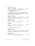
Warning
You must be very careful when programming bidirectional pins for output. If an
external signal is driving a bidirectional pin and you configure the pin for output,
you may cause physical damage to the DAQ-STC, the external circuitry, or both.
7.6.2.1 Parallel Digital I/O
Use the following function to program the value to be output on the DIO pins configured for
output:
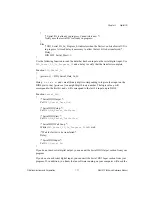
Function
DIO_Parallel_Out
{
DIO_Parallel_Data_Out = [ijklmnop];
}
where i, j, k, l, m, n, o, and p are all binary digits, so that [ijklmnop] is an eight-digit binary
number. Logic values corresponding to i, j, k, l, m, n, o, and p will appear on the DIO pins
configured for output. Note that i corresponds to pin DIO7, j to pin DIO6, and so on. If you
wish to change values on some pins and preserve values on others, you have to maintain a
software copy of the value you write to DIO_Parallel_Data_Out.
Use the following function to read the value from the DIO pins:
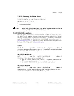
Function
DIO_Parallel_In
{
[ijklmnop] = DIO_Parallel_Data_In_St;
}
Here i, j, k, l, m, n, o, and p are all binary digits corresponding to logic values on the DIO pins
7 through 0, so that [ijklmnop] is an eight-digit binary number. Values corresponding to pins
configured for input will reflect the state of the external digital signal connected to the pin.
Values corresponding to the pins configured for output will reflect the values being output on
those pins.


