Chapter 3
Analog Output Timing/Control
DAQ-STC Technical Reference Manual
3-64
©
National Instruments Corporation
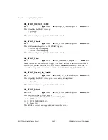
AO_START1_Edge
bit: 5
type: Write
in: AO_Trigger_Select_Register
address: 67
This bit enables edge detection of the START1 trigger:
0: Disabled.
1: Enabled.
This bit should normally be set to 1. Set this bit to 1 if AO_START1_Select is 0. Set this bit
to 0 if the ASIC is a START1 slave to another DAQ-STC.
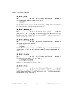
AO_START1_Interrupt_Ack
bit: 9
type: Strobe
in: Interrupt_B_Ack_Register
address: 3
Setting this bit to 1 clears AO_START1_St and acknowledges the START1 interrupt request
(in either interrupt bank) if the START1 interrupt is enabled. This bit is cleared automatically.
Released bitfields: AO_START1_St.
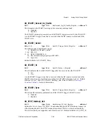
AO_START1_Interrupt_Enable
bit: 1
type: Write
in: Interrupt_B_Enable_Register
address: 75
This bit enables the START1 interrupt:
0: Disabled.
1: Enabled.
The START1 interrupt is generated on valid START1 triggers received by the DAQ-STC.
A valid START1 trigger is one that is received while the BC counter is armed and in the
WAIT1 state.
AO_START1_Polarity
bit: 13
type: Write
in: AO_Trigger_Select_Register
address: 67
This bit determines the polarity of START1 trigger:
0: Active high or rising edge.
1: Active low or falling edge.
Set this bit to 0 if AO_START1_Select is set to 0.
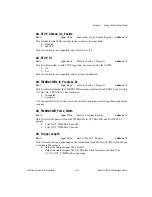
AO_START1_Pulse
bit: 0
type: Strobe
in: AO_Command_2_Register
address: 5
Setting this bit to 1 sends a START1 trigger to the BC, UC, and UI counters if the START1
software strobe is selected (AO_START1_Select is set to 0). This bit is cleared automatically.
Related bitfields: AO_START1_Select.


