


C70 Setup Manual
7.3 Adjustment in Absolute Position Detection System
135
7.3.4 Dog-type Absolute Position Zero Point Initialization Set
Execute the dog-type reference position return with the manual reference position return mode or automatic reference
position return command (G28).
Use GOT project controlled by sequence programs, switches on the machine operation panel, manual handle, and the
[ABS. POSITION SET] screen in the CNC monitor on GOT for the absolute position zero point initialization set. The GOT
project and panel switches are made by the machine tool builder.
(1)
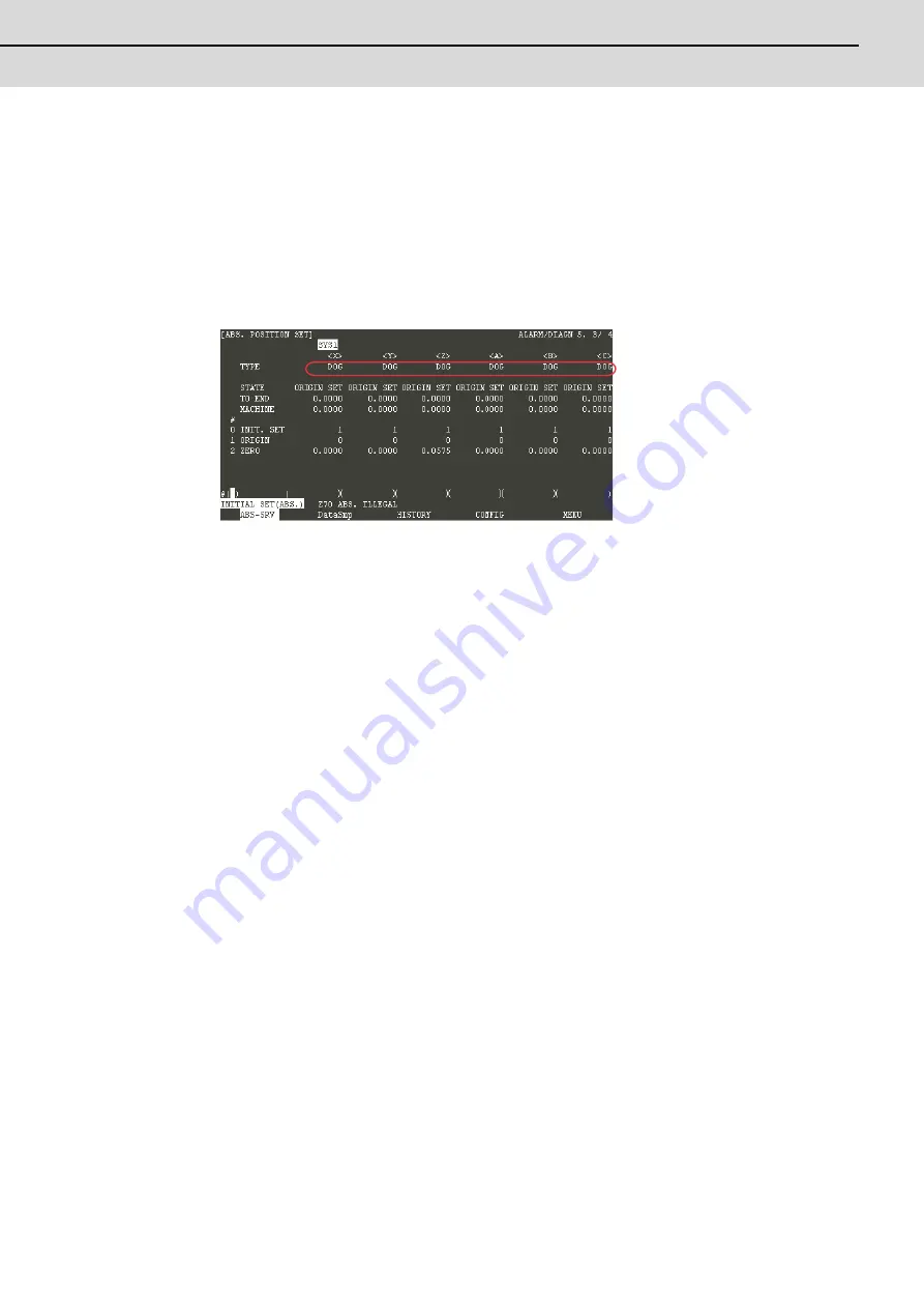
Select [ALARM/DIAGN] ---> [MENU (MENU 5)] ---> [ABS SERVO MONITOR] in the CNC monitor on GOT. Scroll
the page to display the [ABS. POSITION SET] screen.
Check that the "DOG" is applied for the axis for which the absolute position zero point is to be initialized.
(Note)
The type of absolute position zero point initialization set is decided by the machine and axes
specifications, although "DOG" can be selected by setting "3" for "#2049 type Absolute position detection
method". Confirm whether the machine specifications allow the "DOG" before changing the type.
(2)
Perform manual or automatic dog type reference point return.
(3)
The absolute position will be established under the completion of the reference position return. The basic machine
coordinate system will be automatically set.
(4)
Carry out the absolute position initialization set for all the axes, and then turn the power ON again.
(Note 1) If the dog type reference position return is stopped by resetting, the previous state (OK or NG) will be
displayed for "STATE".
(Note 2) The necessary data will be saved in EEROM upon the establishment of the absolute position. The message
notifies that the data is being written in EEROM.
(Note 3) With dog-type, the reference position return can be executed again even if the "STATE" displays "OK".
Summary of Contents for C70
Page 1: ......
Page 3: ......
Page 9: ......
Page 11: ......
Page 13: ......
Page 18: ...1 1 Outline ...
Page 21: ...1 Outline MITSUBISHI CNC 4 ...
Page 22: ...5 2 GOT Initial Setup ...
Page 73: ...2 GOT Initial Setup MITSUBISHI CNC 56 ...
Page 74: ...57 3 PLC CPU Initial Setup ...
Page 91: ...3 PLC CPU Initial Setup MITSUBISHI CNC 74 ...
Page 92: ...75 4 CNC CPU Initial Setup ...
Page 105: ...4 CNC CPU Initial Setup MITSUBISHI CNC 88 ...
Page 106: ...89 5 Connecting and Setting up Multiple CNC CPU Modules ...
Page 115: ...5 Connecting and Setting up Multiple CNC CPU Modules MITSUBISHI CNC 98 ...
Page 116: ...99 6 Setting Machine Parameters ...
Page 130: ...113 7 Setting the Position Detection System ...
Page 153: ...7 Setting the Position Detection System MITSUBISHI CNC 136 ...
Page 154: ...137 8 Deceleration Check ...
Page 159: ...8 Deceleration Check MITSUBISHI CNC 142 ...
Page 160: ...143 9 Setting the Tool Entry Prohibited Range ...
Page 169: ...9 Setting the Tool Entry Prohibited Range MITSUBISHI CNC 152 ...
Page 170: ...153 10 Data Backup and Restoration ...
Page 184: ...167 Appendix 1 Explanation of Parameters ...
Page 435: ...Appendix 1 Explanation of Parameters MITSUBISHI CNC 418 ...
Page 436: ...419 Appendix 2 Explanation of Alarms ...
Page 608: ...591 Appendix 3 Display on 7 segment LED ...
Page 624: ......
Page 628: ......


