C70 Setup Manual
2.2 GT Designer2
53
2.2.6 Transferring the Data to GOT (Using a CF card)
A CF card is also available for installing OS and transferring the project data.
Write OS and the project data into the CF card, and transfer the data to GOT.
2.2.6.1 Writing the Data into a CF card
(1)
Mount a CF card in the personal computer.
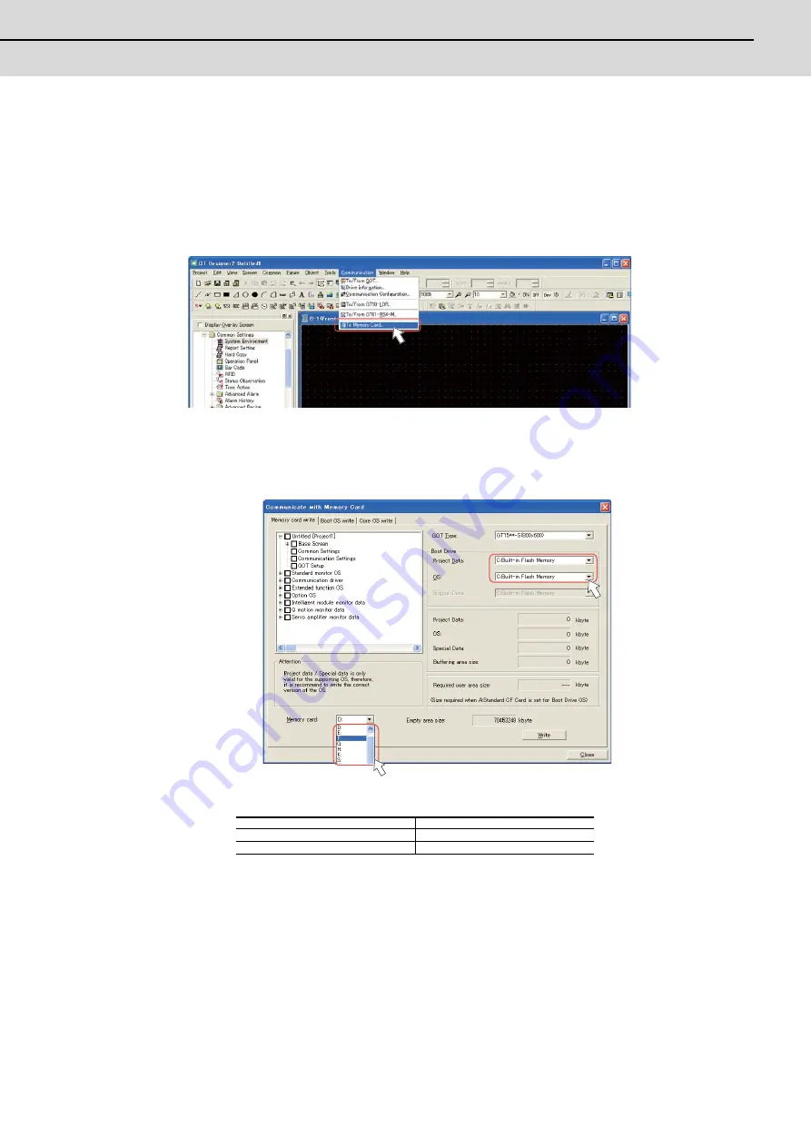
Start GT Designer2 on the personal computer, and open the project. Select [Communication]-[To Memory Card...]
from the menu bar.
(Note)
At starting GT Designer2, if the "New Project Wizard" dialog box appears, close the dialog box.
(2)
Select and set "Boot Drive" and "Memory card".
For "Boot Drive", select the drive on GOT for booting with the project data and OS.
For "Memory card", select the drive assigned to the CF card in the personal computer.
(Note)
The following two options are available for "Boot Drive":
If OS data and project data (drawing data) are larger than the capacity of built-in flash memory, select "A:
Standard CF card" for "Boot Drive".
For details, refer to the "GT Designer2 Version2 Basic Operation/Data Transfer Manual" (SH(NA)-
080529), Section 8.
Project data
OS
A: Standard CF Card
A: Standard CF Card
C: Built-in Flash Memory
C: Built-in Flash Memory
Summary of Contents for C70
Page 1: ......
Page 3: ......
Page 9: ......
Page 11: ......
Page 13: ......
Page 18: ...1 1 Outline ...
Page 21: ...1 Outline MITSUBISHI CNC 4 ...
Page 22: ...5 2 GOT Initial Setup ...
Page 73: ...2 GOT Initial Setup MITSUBISHI CNC 56 ...
Page 74: ...57 3 PLC CPU Initial Setup ...
Page 91: ...3 PLC CPU Initial Setup MITSUBISHI CNC 74 ...
Page 92: ...75 4 CNC CPU Initial Setup ...
Page 105: ...4 CNC CPU Initial Setup MITSUBISHI CNC 88 ...
Page 106: ...89 5 Connecting and Setting up Multiple CNC CPU Modules ...
Page 115: ...5 Connecting and Setting up Multiple CNC CPU Modules MITSUBISHI CNC 98 ...
Page 116: ...99 6 Setting Machine Parameters ...
Page 130: ...113 7 Setting the Position Detection System ...
Page 153: ...7 Setting the Position Detection System MITSUBISHI CNC 136 ...
Page 154: ...137 8 Deceleration Check ...
Page 159: ...8 Deceleration Check MITSUBISHI CNC 142 ...
Page 160: ...143 9 Setting the Tool Entry Prohibited Range ...
Page 169: ...9 Setting the Tool Entry Prohibited Range MITSUBISHI CNC 152 ...
Page 170: ...153 10 Data Backup and Restoration ...
Page 184: ...167 Appendix 1 Explanation of Parameters ...
Page 435: ...Appendix 1 Explanation of Parameters MITSUBISHI CNC 418 ...
Page 436: ...419 Appendix 2 Explanation of Alarms ...
Page 608: ...591 Appendix 3 Display on 7 segment LED ...
Page 624: ......
Page 628: ......


