Appendix 2 Explanation of Alarms
MITSUBISHI CNC
568
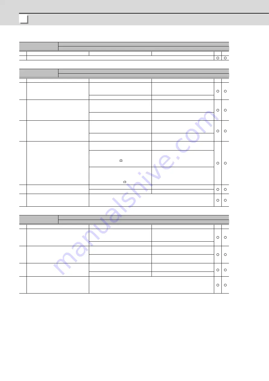
Alarm No.
39
NC-DRV communication: Protocol error 2
An error was detected in the axis information data received from the CNC.
Investigation details
Investigation results
Remedies
SV
SP
1
Check the alarm No. "34" items.
Alarm No.
3A
Overcurrent
Excessive current was detected in the motor drive current.
Investigation details
Investigation results
Remedies
SV
SP
1
[1] Check whether vibration is occurring at
the table or spindle.
[2] Check if the vibration caused by the load
fluctuation is occurring.
Vibration is occurring.
[1] Set a filter.
[2] Lower the speed loop gain (SV005/
SP005).
There is no vibration.
Check the investigation item No. 2.
2
Check the repeatability of the alarm at the
rapid traverse feed for the servo and at
acceleration/deceleration for the spindle.
(Note) Check the phenomenon caused by
the load fluctuation.
The alarm occurs.
Lower the speed loop gain (SV005/SP005)
to the level at which the alarm does not
occur.
The alarm does not occur.
Check the investigation item No. 3.
3
For the servo, perform the rapid traverse
feed repeatedly and check if the max.
current value is within the tolerable value.
For the spindle, check the load meter value
at the unloaded max. rotation speed.
The displayed value is high.
Increase the current loop gain.
Servo: SV009 to 012
Spindle: SP077 to 080 and SP081 to 084
The displayed value is appropriate.
Check the investigation item No. 4.
4
Disconnect the power cable (U,V,W) from
the terminal block and the cannon plug from
the motor. Check the insulation of the cable
and motor with a tester.
The resistance value of the power cable for
each phase is not "
∞
".
Replace the motor power cable.
The resistance value of the motor terminal
and unit (shaft) is 1M
or less.
Replace the motor.(Note) For the motors
equipped with the absolute position
detector, the zero point must be
established.
The values below are met when measured
with a tester.
Cable:
∞
Motor terminal - unit:1M
or more
Check the investigation item No. 5.
5
Check the insulation between the motor
power cable and FG.
There is a ground fault at the power cable.
Replace the motor power cable.
There is no problem.
Check the investigation item No. 6.
6
Check if there is any abnormality in the
motor's ambient environment.
(Ex. Ambient temperature, cutting water)
Take remedies according to the causes of the abnormality in the ambient environment.
Alarm No.
3B
Power module overheat
Thermal protection function in the power module has started its operation.
Investigation details
Investigation results
Remedies
SV
SP
1
Check that the fan of the drive unit is rotating
correctly.
Large amounts of cutting oil or cutting chips,
etc., are adhered to the fan, or the rotation
is slow.
Clean or replace the fan.
The fan is rotating properly.
Check the investigation item No. 2.
2
Check whether the heat dissipating fins are
dirty.
Cutting oil or cutting chips, etc., are
adhered, and the fins are clogged.
Clean the fins.
Cutting chips etc. are not adhered to the
fins.
Check the investigation item No. 3.
3
Measure the drive unit's ambient
temperature.
55
°
C or more.
Improve the efficiency cooling for the power
distribution panel.
Less than 55
°
C.
Check the investigation item No. 4.
4
Check if there is any abnormality in the
unit's ambient environment.
(Ex. Ambient temperature, noise,
grounding)
Take remedies according to the causes of the abnormality in the ambient environment.
Summary of Contents for C70
Page 1: ......
Page 3: ......
Page 9: ......
Page 11: ......
Page 13: ......
Page 18: ...1 1 Outline ...
Page 21: ...1 Outline MITSUBISHI CNC 4 ...
Page 22: ...5 2 GOT Initial Setup ...
Page 73: ...2 GOT Initial Setup MITSUBISHI CNC 56 ...
Page 74: ...57 3 PLC CPU Initial Setup ...
Page 91: ...3 PLC CPU Initial Setup MITSUBISHI CNC 74 ...
Page 92: ...75 4 CNC CPU Initial Setup ...
Page 105: ...4 CNC CPU Initial Setup MITSUBISHI CNC 88 ...
Page 106: ...89 5 Connecting and Setting up Multiple CNC CPU Modules ...
Page 115: ...5 Connecting and Setting up Multiple CNC CPU Modules MITSUBISHI CNC 98 ...
Page 116: ...99 6 Setting Machine Parameters ...
Page 130: ...113 7 Setting the Position Detection System ...
Page 153: ...7 Setting the Position Detection System MITSUBISHI CNC 136 ...
Page 154: ...137 8 Deceleration Check ...
Page 159: ...8 Deceleration Check MITSUBISHI CNC 142 ...
Page 160: ...143 9 Setting the Tool Entry Prohibited Range ...
Page 169: ...9 Setting the Tool Entry Prohibited Range MITSUBISHI CNC 152 ...
Page 170: ...153 10 Data Backup and Restoration ...
Page 184: ...167 Appendix 1 Explanation of Parameters ...
Page 435: ...Appendix 1 Explanation of Parameters MITSUBISHI CNC 418 ...
Page 436: ...419 Appendix 2 Explanation of Alarms ...
Page 608: ...591 Appendix 3 Display on 7 segment LED ...
Page 624: ......
Page 628: ......


