Navigational page layout
Version 6.03, May 2017
Page 154 of 192
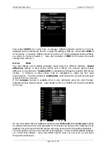
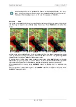
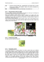
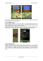
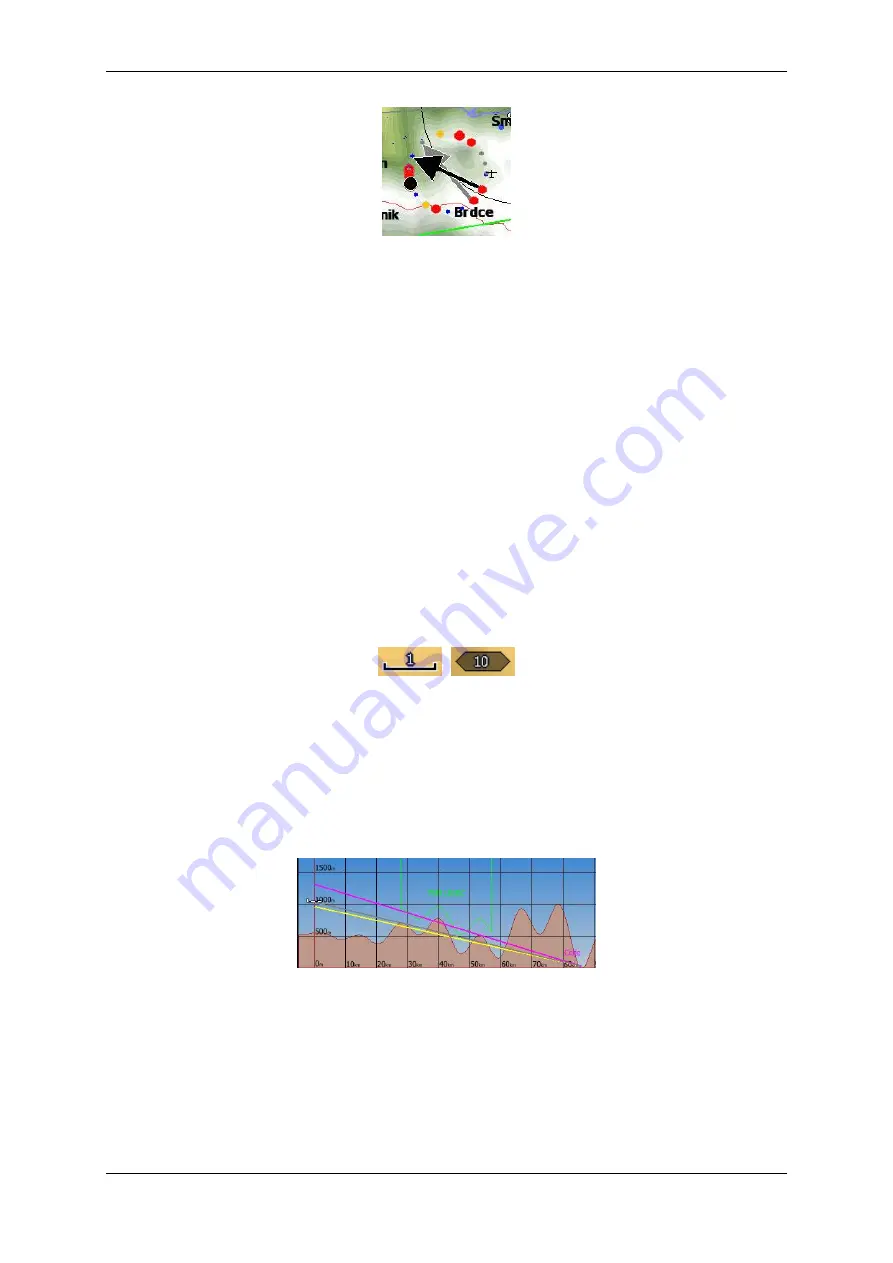
The thermal assistant continuously analyses the thermal whilst circling. The sizes of the
dots indicate the strength of the thermal. Big dots mean stronger lift at that point. On the
left or right side of the circle a small airplane symbol is shown. This airplane indicates your
position. A black dot indicates the thermal maximum. The pilot should extend the circle
when the black dot is about 60° away from glider. This value varies and depends on turn
rate of the glider and type of thermal. All other dots are coloured based on the MacCready
setting. Red colour means values above MacCready, blue values below MacCready and
yellow dots represents lift about the same strength as the MacCready setting.
This colour scheme gives us hints about a thermal at glance. If most of dots are red we
should consider increasing the MacCready value; if most of dots are blue we should consider
decreasing the MacCready setting.
6.3.8
Zoom
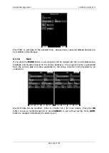
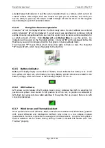
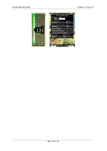
Zoom symbol shows current map zoom. It can be used only when the map symbol is
already on the page. Zoom can be presented in two ways; number on symbol indicates the
length of the zoom symbol or number indicates length of whole screen. You can toggle
“Show full screen distance” property to change this setting. Displayed value is given in
distance units (km, nm or mi).
6.3.9
Side View
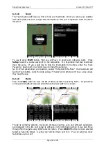
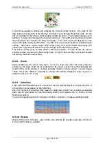
This symbol shows lateral view of our position toward selected target or bearing of plane. It
shows terrain and airspaces in that direction.
Grey line represents projected track based on glide ratio. Yellow line is showing requested
glide ratio to goal based on zero MacCready setting and magenta line is showing current
MacCready setting.
You can change appearance of airspaces in Setup > Graphics > Airspaces settings dialog.
6.3.10
Picture
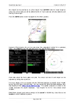
Waypoint files with extension .cupx include also pictures for specific waypoints, which can
be seen if this option is enabled.


