


6. Safety Functions
6-5
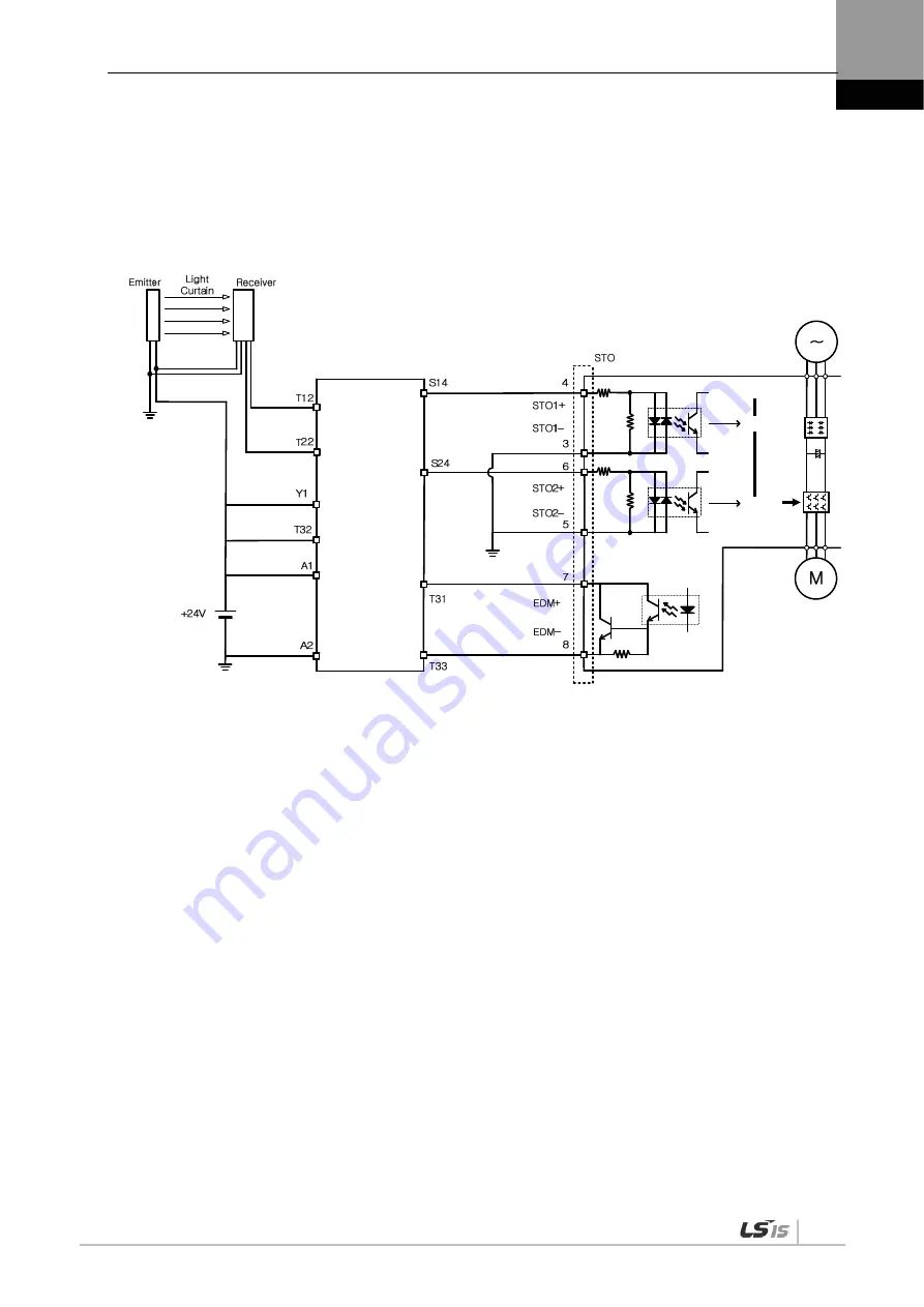
6.3
Example of Using Safety Function
6.4
How to Verify Safety Function
In case that the servo drive was replaced prior to the device startup or during maintenance, make sure
to check the details below:
When STO1 and STO2 signals are turned OFF, check if the drive is in STO status (Bit 31 of digital
input (0x60FD) is 1).
Make sure that the EDM signal is off during general operation by checking the input indicator for
feedback circuit of the connected device.
Blocking
Safety unit
Driving signal
Blocking
EDM output
Summary of Contents for XDL-L7NH Series
Page 2: ......
Page 12: ......
Page 21: ...1 Product Configuration 1 9 1 3 2 Servo Motor Parts 80 Flange or below 130 Flange or higher ...
Page 43: ...2 Wiring and Connection 2 21 ...
Page 58: ......
Page 68: ......
Page 75: ...4 CiA402 Drive Profile 4 7 Internal Block Diagram of CSP Mode ...
Page 78: ...4 CiA402 Drive Profile 4 10 Internal Block Diagram of PP Mode ...
Page 86: ...4 CiA402 Drive Profile 4 18 Internal Block Diagram of PV Mode ...
Page 118: ...5 Drive Application Functions 5 10 ...
Page 148: ......
Page 283: ...10 Product Specifications 10 23 SGP Series APM SGP110G ...
Page 284: ...10 Product Specifications 10 24 SGP Series APM SGP150G ...
Page 288: ...10 Product Specifications 10 28 FGP Series APM FGP110G ...
Page 294: ...10 Product Specifications 10 34 XDL L7NHB150U Weight 15 5 kg including the cooling fan ...
Page 336: ...13 Appendix 13 20 5 Turn on the power again and verify if the firmware is updated ...
Page 346: ......