


5. Drive Application Functions
5-31
5.10.2
P/PI Control Switching
PI control uses both proportional (P) and integral (I) gains of the speed controller, while P control uses
only proportional gain.
The proportional gain determines the responsiveness of the entire controller, and the integral gain is
used to eliminate an error in the steady state. Too high of an integral gain will result in an overshoot
during acceleration or deceleration.
The PI/P control switching functions are used to switch between the PI and P controls under the
condition of the parameters within the servo (such as torque, speed, acceleration, and position
deviation); specifically, they are used under the following situations:
Speed control: To suppress any overshoot or undershoot during acceleration/deceleration.
Position control: To suppress undershoot during positioning, resulting in a reduced positioning time.
You can accomplish similar effect by setting the acceleration/deceleration of the upper level controller,
the soft start of the servo drive, the position command filter, or etc.
You can configure these settings in the P/PI control switching mode (0x2114). Please see the details
below: Switching to P control by PCON input takes precedence over this setting.
Setting values
Setting details
0
Always uses the PI control.
1
Switches to the P control if the command torque is larger than the P
control switching torque (0x2115).
2
Switches to the P control if the command speed is larger than the P
control switching speed (0x2116).
3
Switches to the P control if the acceleration command is larger than the P
control switching acceleration (0x2117).
4
Switches to the P control if the position error is larger than the P control
switching position error (0x2118).
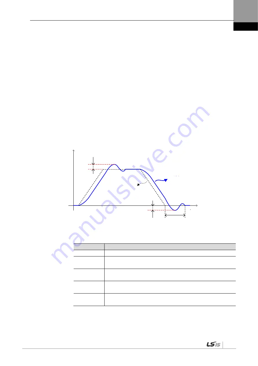
Positioning time
Speed
Time
Overshoot
Motor speed
Speed
Command
Undershoot
Summary of Contents for XDL-L7NH Series
Page 2: ......
Page 12: ......
Page 21: ...1 Product Configuration 1 9 1 3 2 Servo Motor Parts 80 Flange or below 130 Flange or higher ...
Page 43: ...2 Wiring and Connection 2 21 ...
Page 58: ......
Page 68: ......
Page 75: ...4 CiA402 Drive Profile 4 7 Internal Block Diagram of CSP Mode ...
Page 78: ...4 CiA402 Drive Profile 4 10 Internal Block Diagram of PP Mode ...
Page 86: ...4 CiA402 Drive Profile 4 18 Internal Block Diagram of PV Mode ...
Page 118: ...5 Drive Application Functions 5 10 ...
Page 148: ......
Page 283: ...10 Product Specifications 10 23 SGP Series APM SGP110G ...
Page 284: ...10 Product Specifications 10 24 SGP Series APM SGP150G ...
Page 288: ...10 Product Specifications 10 28 FGP Series APM FGP110G ...
Page 294: ...10 Product Specifications 10 34 XDL L7NHB150U Weight 15 5 kg including the cooling fan ...
Page 336: ...13 Appendix 13 20 5 Turn on the power again and verify if the firmware is updated ...
Page 346: ......