2
D
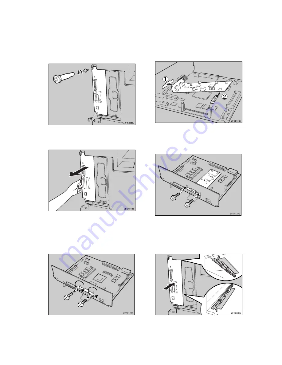
Remove the two screws locking
the printer board.
The screws are needed to lock the
printer board afterwards.
E
Hold the handle, and carefully
pull out the printer board.
F
Put the printer board on a flat sur-
face.
G
Remove the two screws locking
the 1394 Interface Unit cover.
The screws are needed to lock the
1394 Interface Unit afterwards.
H
Attach the 1394 Interface Unit to
the slot. Confirm that the unit is
firmly connected to the printer
board.
I
Lock the 1394 Interface Unit cover
with the two screws you removed
in step
G
.
J
Align the printer board with the
top and bottom rails in the print-
er, and then insert the printer
board slowly until it stops.
Summary of Contents for AP4510
Page 1: ...Setup Guide...
Page 10: ...viii...
Page 40: ...Installing Options 30 2...
Page 46: ...Configuring the Printer for the Network 36 3...
Page 66: ...56 UE USA G065 MEMO...
Page 92: ...Setting Up the Printer Driver and Canceling a Print Job 18 1...
Page 118: ...Paper and Other Media 44 3...
Page 128: ...Sample Print Locked Print 54 4...
Page 206: ...Making Printer Settings with the Control Panel 132 6...
Page 225: ......
Page 226: ...UE USA G065 8667...
Page 240: ...xii...
Page 252: ...Windows 95 98 Me Configuration 12 1...
Page 278: ...Windows NT 4 0 Configuration 38 3...
Page 338: ...98 UE USA EE GB G065...
Page 339: ...Copyright 2001...
Page 340: ...Network Printing Guide UE USA EE GB G065 8605...
Page 344: ...ii...
Page 370: ...26 UE USA EE GB G065...
Page 371: ...Copyright 2001...
Page 372: ...PostScript 3 Operating Instructions Supplement UE USA EE GB G065 8615...
Page 373: ...UNIX Supplement...
Page 408: ...32 EE GB G065...
Page 409: ...Copyright 2001...
Page 410: ...UNIX Supplement EE GB...
Page 418: ...8 Copyright 2001 G065 8537 Printed in Japan UE USA EE GB...


