Copyright© 2001 G790-8610 Printed in China
UE USA EE GB
○
○
○○○○○○○○○○○
○○○○○○○
○○○○○
○○○○○○○○○○○○○○
○
○
○○○○○○○○
○○○○○○○○○○○○○○
○○○○○○○○○○○○○
○○○○○○○
○
○
○○○○
○
○
○
○○○○○
○○○○○○○○○○○○○○○
○○○○○○○○○○
○○○○○○○
○○○○○○○○
○○○○○○○○○○○○
○○○○○○○○○○○
○○○○○
○○○○○○○○○○○○○○○○
○○○○○○○
○
○○○○○○○○○
○○○○○○○○○○○○○○○
○○○○○○
○○○○○○○○○
○○○○○○○○○○
○○○○○
○○○
○○○○○○
○○○○○○○○○○○○
○○○○
○○○○○○○○○○○○○○○
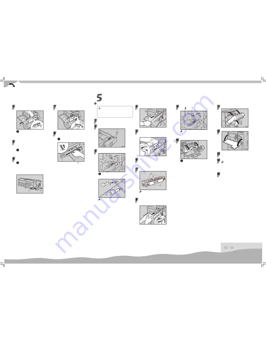
REPLACING THE FUSING UNIT
CAUTION
•
The fusing unit becomes very hot. When installing the new fusing
unit, turn off the printer and wait for about 30 minutes. After waiting,
install the new fusing unit. Not waiting for the unit to cool down can
result in a burn injury.
Be sure to wait 30 minutes after turning off the printer,
and confirm that it is cool before continuing.
Pull out the standard paper tray (Tray 1), and take the
screwdriver (
a
) from the tray.
Remove the screw inside the front cover (
a
) by turning it
counterclockwise to release the fusing unit.
ZFCM090E
Important
❒
When removing the screw, press the screwdriver onto the screw
until it makes an audible click as it pops into place.
TAPP761E
Note
❒
You need the screw to lock the new fusing unit afterwards.
Hold the green handle (
a
), and slide out the development
unit (
b
). Put the used development unit in the disposal
bag.
ZFCM060J
Important
❒
After removing the development unit, put the unit in the
disposal bag. Be careful not to tilt or shake the unit, otherwise,
toner might scatter.
Take the new development unit from the Type 4510A box.
Before taking the development unit from the box, be sure to read
the “Removing the Development Unit from the Box” sheet in the
Type 4510A box and follow the instructions.
Important
❒
After taking the new development unit from the box, be careful
not to shake or jar the unit.
Remove the tape with the red tag (
a
) and the transparent
tape (
b
).
Important
❒
While pulling out the tape, keep the development unit
horizontal, as shown in the illustration. Tilting or shaking
the unit might cause the toner to scatter.
❒
Do not remove the black sheet until you finish installing the
unit. The black sheet is used to protect the green part of the
development unit.
ZFCM080J
Align the new development unit with the rail in the printer.
Slide the development unit into the printer until it makes a
click as it locks into place.
ZFCM070J
At the right side of the printer, remove the tape on the left
and right sides of the black sheet, and then pull out the
sheet using both hands.
Important
❒
Do not toucth the green part protected by the black sheet.
TAPM090E
Leave the right cover open, and go to “ REPLACING THE FUSING
UNIT”.
Lock the fusing unit in place with the screw you removed
in step
.
ZFCM130E
Note
❒
Be sure to return the screwdriver to the paper tray after using
it.
Close the right cover.
ZFCH192E
Important
❒
Do not force the right cover to close. If you cannot close it
easily, confirm that the development unit and the fusing unit
are installed correctly, and that the transfer unit is locked
correctly.
Hold the blue knob, and slowly pull the fusing unit out until
the whole of the green handle is visible.
ZFCM100E
There is the green lever (
a
) on the left side of the fusing
unit. While pressing the green lever to the left, slide the
fusing unit out slowly with rasing the green handle and
holding it.
ZFCM110E
Take the new fusing unit from the Type 4510B box and
remove the plastic bag.
Remove the two pins with red tag (
a
), the three
transparent tapes (
b
) and the desiccant (
c
).
ZFCM140J
Note
❒
There is another transparent tape at the bottom of the fusing
unit, make sure to remove the transparent tape.
Place the green handle in the fusing unit. Hold the new
fusing unit with both hands, and keep the unit horizontal.
Align the unit with the rail in the printer (
a
), and then
slide the fusing unit into the printer until it stops.
ZFCM120E
Close the duplex unit (
a
), and then close the bypass tray
(
b
).
Close the front cover.
Take the gloves off.
Turn the printer’s power switch on.
Note
❒
The first time you turn the printer on after installation or after
replacing the photoconductor unit, it will make several loud
noises. This is due to the photoconductor unit initializing and
is perfectly normal.
Confirm that the "Change Maint.Kit" message on the
operation panel has cleared.
Replacing the maintenance kit is finished.
Summary of Contents for AP4510
Page 1: ...Setup Guide...
Page 10: ...viii...
Page 40: ...Installing Options 30 2...
Page 46: ...Configuring the Printer for the Network 36 3...
Page 66: ...56 UE USA G065 MEMO...
Page 92: ...Setting Up the Printer Driver and Canceling a Print Job 18 1...
Page 118: ...Paper and Other Media 44 3...
Page 128: ...Sample Print Locked Print 54 4...
Page 206: ...Making Printer Settings with the Control Panel 132 6...
Page 225: ......
Page 226: ...UE USA G065 8667...
Page 240: ...xii...
Page 252: ...Windows 95 98 Me Configuration 12 1...
Page 278: ...Windows NT 4 0 Configuration 38 3...
Page 338: ...98 UE USA EE GB G065...
Page 339: ...Copyright 2001...
Page 340: ...Network Printing Guide UE USA EE GB G065 8605...
Page 344: ...ii...
Page 370: ...26 UE USA EE GB G065...
Page 371: ...Copyright 2001...
Page 372: ...PostScript 3 Operating Instructions Supplement UE USA EE GB G065 8615...
Page 373: ...UNIX Supplement...
Page 408: ...32 EE GB G065...
Page 409: ...Copyright 2001...
Page 410: ...UNIX Supplement EE GB...
Page 418: ...8 Copyright 2001 G065 8537 Printed in Japan UE USA EE GB...


