


371
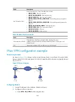
Figure 368
Network diagram
Configure the VPN user
Assign an IP address (2.1.1.1 in this example) to the user host, configure a route to ensure the reachability
of the LNS (1.1.2.2), and create a virtual private network connection using the Windows operating system,
or install L2TP client software such as WinVPN Client and connect to the Internet in dial-up mode. Then,
perform the following configurations (the configuration order varies with the client software):
•
Specify the VPN username as
vpdnuser
and the password as
Hello
.
•
Set the Internet interface address of the security gateway as the IP address of the LNS. In this
example, the Ethernet interface on the LNS, the interface for the tunnel, has an IP address of 1.1.2.2.
•
Modify the connection attributes, setting the protocol to
L2TP
, the encryption attribute to
customized
and the authentication mode to
CHAP
.
Configure the LNS
Before you perform the following configurations, configure IP addresses for interfaces and make sure the
LNS and the user host can reach each other.
1.
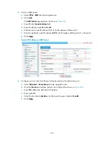
Create a local user:
a.
Select
System Management
>
Users
from the navigation tree.
b.
Click the
Create User
tab.
The local user configuration page appears, as shown in
.
c.
Enter
vpdnuser
as the username.
d.
Select access level
Configure
.
e.
Enter password
Hello
.
f.
Enter
Hello
to confirm the password.
g.
Select
PPP
as the service type.
h.
Click
Apply
.
Summary of Contents for MSR SERIES
Page 17: ...xv Documents 835 Websites 835 Conventions 836 Index 838 ...
Page 20: ...3 Figure 3 Initial page of the Web interface ...
Page 42: ...25 Figure 13 Firefox Web browser setting ...
Page 59: ...42 Figure 27 Checking the basic service configuration ...
Page 73: ...56 Figure 35 Sample interface statistics ...
Page 156: ...139 Figure 139 Rebooting the 3G modem ...
Page 168: ...151 Figure 152 Configuring Web server 2 ...
Page 174: ...157 Figure 158 Configure the URL filtering function ...
Page 242: ...225 Figure 233 Enabling the DHCP client on interface Ethernet 0 1 ...
Page 247: ...230 Figure 236 The page for configuring an advanced IPv4 ACL ...
Page 255: ...238 Figure 241 Advanced limit setting ...
Page 298: ...281 e Click Apply 2 Configure Router B in the same way Router A is configured ...
Page 400: ...383 Figure 387 Verifying the configuration ...
Page 405: ...388 ...
Page 523: ...506 Figure 530 Ping configuration page ...
Page 775: ...758 Figure 785 Configuring a jump node ...


