


618
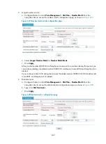
2.
Type 1100.. for
Numbers in the Group
.
3.
Click
Add
to add numbers into the group.
4.
Click
Apply
.
Enter the number group configuration page again to add another number group:
5.
Type 2 for
Group ID
.
6.
Type 1200.. for
Numbers in the Group
.
7.
Click
Add
to add numbers into the group.
8.
Click
Apply
.
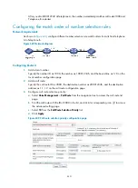
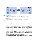
# Add a call route for place B: specify the call route ID as 2000, the destination number as 2..., and use
a proxy server for SIP routing on the call route configuration page.
# Crete a call route for place C: specify the call route ID as 3000, the destination number as 3...,and use
a proxy server for SIP routing on the call route configuration page.
# Add a call route for place B: specify the call route ID as 2100, the destination number as 2…, and trunk
route line as 5/0:15 on the call route configuration page. In addition, you need to select the
Send All
Digits of a Called Number
option in the
Called Number Sending Mode
area when you configure the
advanced settings of this call route.
# Add a call route 3… for place C: specify the call route ID as 3100, the destination number as 3..., and
the trunk route line as 5/1:15 on the call route configuration page. In addition, you need to select the
Send All Digits of a Called Number
option in the
Called Number Sending Mode
area when you
configure the advanced settings of this call route.
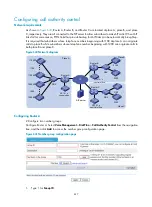
# Bind a call route to number group 1 to allow that subscribers whose telephone numbers beginning with
1100 at place A can originate calls to place B.
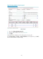
Select
Voice Management
>
Dial Plan
>
Call Authority Control
from the navigation tree to access the
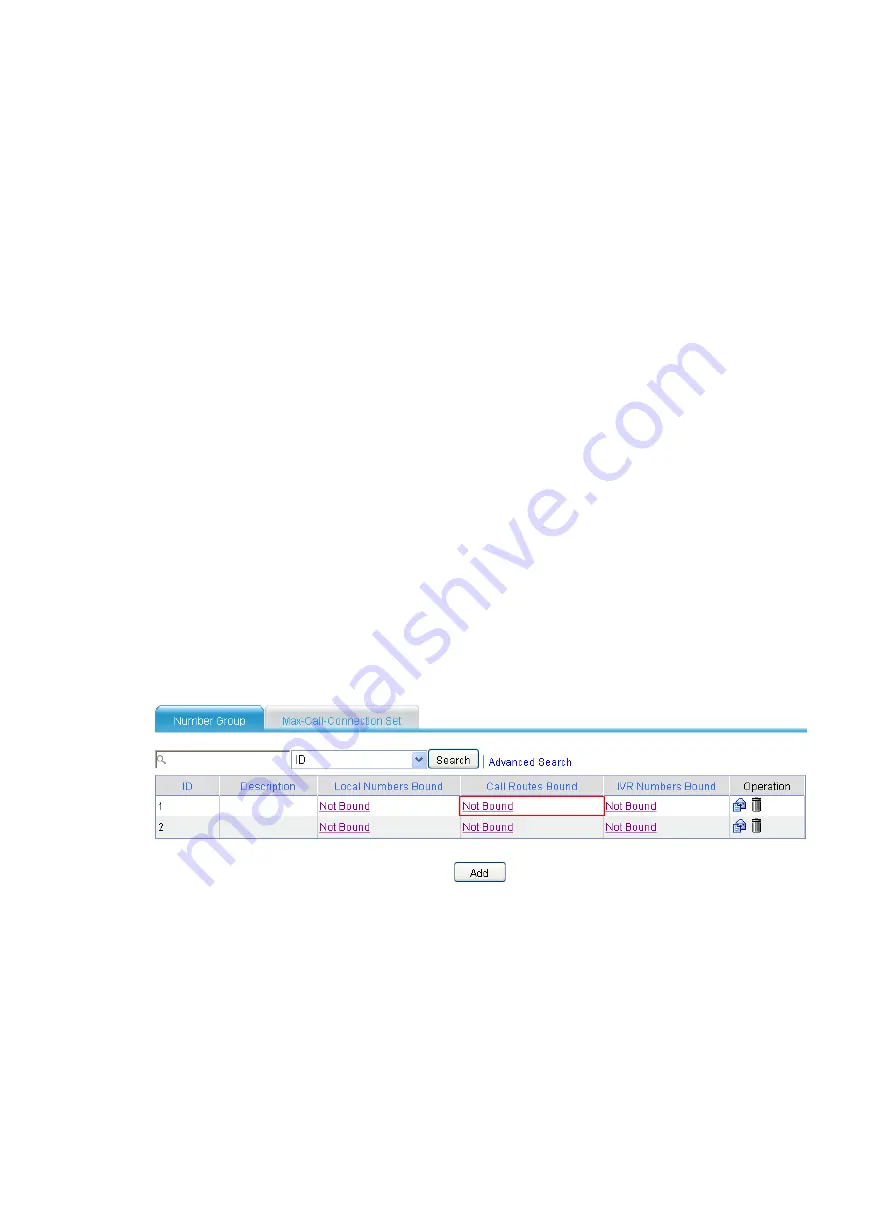
page as shown in
Figure 642
Binding call route configuration page (I)
Click
Not Bound
in the
Call Routes Bound
column to access the call route binding page of number group
1.
Summary of Contents for MSR SERIES
Page 17: ...xv Documents 835 Websites 835 Conventions 836 Index 838 ...
Page 20: ...3 Figure 3 Initial page of the Web interface ...
Page 42: ...25 Figure 13 Firefox Web browser setting ...
Page 59: ...42 Figure 27 Checking the basic service configuration ...
Page 73: ...56 Figure 35 Sample interface statistics ...
Page 156: ...139 Figure 139 Rebooting the 3G modem ...
Page 168: ...151 Figure 152 Configuring Web server 2 ...
Page 174: ...157 Figure 158 Configure the URL filtering function ...
Page 242: ...225 Figure 233 Enabling the DHCP client on interface Ethernet 0 1 ...
Page 247: ...230 Figure 236 The page for configuring an advanced IPv4 ACL ...
Page 255: ...238 Figure 241 Advanced limit setting ...
Page 298: ...281 e Click Apply 2 Configure Router B in the same way Router A is configured ...
Page 400: ...383 Figure 387 Verifying the configuration ...
Page 405: ...388 ...
Page 523: ...506 Figure 530 Ping configuration page ...
Page 775: ...758 Figure 785 Configuring a jump node ...


