


721
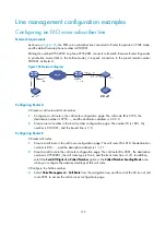
Figure 738
Network diagram
Configuration considerations
•
Configure one-to-one binding between FXS and FXO voice subscriber lines.
•
When the IP network is available, the VoIP entity is preferably used to make calls over the IP
network.
•
When the IP network is unavailable, the POTS entity is used to make calls through the bound FXO
voice subscriber line over the PSTN.
Configuration procedure
Router A and Router B are routable to each other.
The configuration of interface IP addresses is not shown.
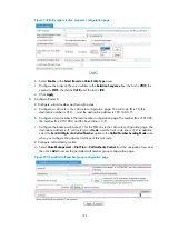
1.
Configure Router A:
# Configure a local number and two call routes.
a.
Configure a call route in the call route configuration page: The call route ID is 210, the
destination number is 210…., and the destination address is 192.168.0.76.
b.
Configure a local number in the local number configuration page: The number ID is 0101001,
the number is 0101001, and the bound line is 3/0.
c.
Configure the backup call route 211 for the FXO line in the call route configuration page: The
destination address is
.T
, call route type is
Trunk
, and the trunk route line is 4/0. In addition,
select the
Send All Digits of a Called Number
option in the
Called Number Sending Mode
area
when you configure the advanced settings of this call route.
# Configure call authority control.
d.
Select
Voice Management
>
Dial Plan
>
Call Authority Control
from the navigation tree, and
then click
Add
to access the permitted call number group configuration page.
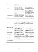
Summary of Contents for MSR SERIES
Page 17: ...xv Documents 835 Websites 835 Conventions 836 Index 838 ...
Page 20: ...3 Figure 3 Initial page of the Web interface ...
Page 42: ...25 Figure 13 Firefox Web browser setting ...
Page 59: ...42 Figure 27 Checking the basic service configuration ...
Page 73: ...56 Figure 35 Sample interface statistics ...
Page 156: ...139 Figure 139 Rebooting the 3G modem ...
Page 168: ...151 Figure 152 Configuring Web server 2 ...
Page 174: ...157 Figure 158 Configure the URL filtering function ...
Page 242: ...225 Figure 233 Enabling the DHCP client on interface Ethernet 0 1 ...
Page 247: ...230 Figure 236 The page for configuring an advanced IPv4 ACL ...
Page 255: ...238 Figure 241 Advanced limit setting ...
Page 298: ...281 e Click Apply 2 Configure Router B in the same way Router A is configured ...
Page 400: ...383 Figure 387 Verifying the configuration ...
Page 405: ...388 ...
Page 523: ...506 Figure 530 Ping configuration page ...
Page 775: ...758 Figure 785 Configuring a jump node ...


