


739
Verifying the configuration
•
When the VCX fails, the local SIP server on Router A starts to accept registrations from phones,
which then can call each other through Router A. Select
Voice Management
>
States and Statistics
>
Local Survival Service States
from the navigation tree. You can find that numbers 1000 and 5000
have been registered with the local SIP server on Router A.
•
When the VCX recovers, Router A disables the local SIP server, and the phones register with the
VCX again.
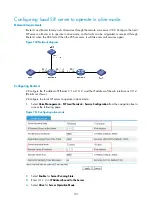
Configuring call authority control
Network requirements
The numbers for Department A in a company are in the range of 1000 to 1999, while those for
Department B are in the range of 5000 to 5999. The following restrictions need to be implemented:
•
Phones in Department A and Department B cannot originate external calls.
•
Phone 5000 is not allowed to call phone 1000.
Figure 763
Network diagram
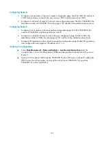
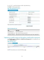
Configuring the local SIP server on Router C
# Configure the local SIP server to operate in alone mode.
1.
Select
Voice Management
>
SIP Local Survival
>
Service Configuration
from the navigation tree to
access the following page.
Summary of Contents for MSR SERIES
Page 17: ...xv Documents 835 Websites 835 Conventions 836 Index 838 ...
Page 20: ...3 Figure 3 Initial page of the Web interface ...
Page 42: ...25 Figure 13 Firefox Web browser setting ...
Page 59: ...42 Figure 27 Checking the basic service configuration ...
Page 73: ...56 Figure 35 Sample interface statistics ...
Page 156: ...139 Figure 139 Rebooting the 3G modem ...
Page 168: ...151 Figure 152 Configuring Web server 2 ...
Page 174: ...157 Figure 158 Configure the URL filtering function ...
Page 242: ...225 Figure 233 Enabling the DHCP client on interface Ethernet 0 1 ...
Page 247: ...230 Figure 236 The page for configuring an advanced IPv4 ACL ...
Page 255: ...238 Figure 241 Advanced limit setting ...
Page 298: ...281 e Click Apply 2 Configure Router B in the same way Router A is configured ...
Page 400: ...383 Figure 387 Verifying the configuration ...
Page 405: ...388 ...
Page 523: ...506 Figure 530 Ping configuration page ...
Page 775: ...758 Figure 785 Configuring a jump node ...