314
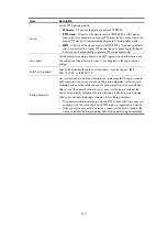
Item Description
Timers
Set the timers:
•
Forward Delay
—Set the delay for the root and designated ports to transit to
the forwarding state. The length of the forward delay time is related to the
network diameter of the switched network. The larger the network diameter
is, the longer the forward delay time should be. If the forward delay setting
is too small, temporary redundant paths might be introduced. If the forward
delay setting is too big, it might take a long time for the network to
converge. HP recommends that you use the default setting.
•
Hello Time
—Set the interval at which the device sends hello packets to the
surrounding devices to make sure the paths are fault-free. A correct hello
time setting enables the device to timely detect link failures on the network
without using excessive network resources. If the hello time is set too long,
the device will take packet loss as a link failure and trigger a new spanning
tree calculation process. If the hello time is set too short, the device will send
repeated configuration BPDUs frequently. This adds to the device burden
and wastes network resources. HP recommends that you use the default
setting.
•
Max Age
—Set the maximum length of time a configuration BPDU can be
held by the device. If the max age time setting is too small, the network
devices will frequently launch spanning tree calculations and might take
network congestion as a link failure. If the max age setting is too large, the
network might fail to timely detect link failures and fail to timely launch
spanning tree calculations, reducing the auto-sensing capability of the
network. HP recommends that you use the default setting.
When you configure timers, follow these guidelines:
•
The settings of hello time, forward delay and max age must meet a certain
formula. Otherwise, the network topology will not be stable. HP
recommends you to set the network diameter, and then have the device
automatically calculate the forward delay, hello time, and max age.
•
The bridge diameter cannot be configured together with the timers.
Instance
•
Instance
ID
—Set the ID of the MSTI to be configured.
•
Root
Type
—Set the role of the device in the MSTI:
Not Set
—The device role is not configured.
Primary
—Configure the device as the root bridge.
Secondary
—Configure the device as a secondary root bridge.
•
Bridge Priority
—Set the bridge priority of the device, which is one of the
factors determining whether the device can be elected as the root bridge.
After specifying the current device as the primary root bridge or a secondary
root bridge, you cannot change the priority of the device.
TC Protection
Select whether to enable TC-BPDU guard.
When receiving topology change (TC) BPDUs, the device flushes its
forwarding address entries. If someone forges TC-BPDUs to attack the device,
the device will receive a large number of TC-BPDUs within a short time and
frequently flushes its forwarding address entries. This affects network stability.
The TC-BPDU guard function prevents frequent flushing of forwarding address
entries.
HP recommends not disabling this function.
TC Protection Threshold
Set the maximum number of immediate forwarding address entry flushes the
device can perform within a certain period of time after receiving the first
TC-BPDU.
Summary of Contents for MSR SERIES
Page 17: ...xv Documents 835 Websites 835 Conventions 836 Index 838 ...
Page 20: ...3 Figure 3 Initial page of the Web interface ...
Page 42: ...25 Figure 13 Firefox Web browser setting ...
Page 59: ...42 Figure 27 Checking the basic service configuration ...
Page 73: ...56 Figure 35 Sample interface statistics ...
Page 156: ...139 Figure 139 Rebooting the 3G modem ...
Page 168: ...151 Figure 152 Configuring Web server 2 ...
Page 174: ...157 Figure 158 Configure the URL filtering function ...
Page 242: ...225 Figure 233 Enabling the DHCP client on interface Ethernet 0 1 ...
Page 247: ...230 Figure 236 The page for configuring an advanced IPv4 ACL ...
Page 255: ...238 Figure 241 Advanced limit setting ...
Page 298: ...281 e Click Apply 2 Configure Router B in the same way Router A is configured ...
Page 400: ...383 Figure 387 Verifying the configuration ...
Page 405: ...388 ...
Page 523: ...506 Figure 530 Ping configuration page ...
Page 775: ...758 Figure 785 Configuring a jump node ...


