


130
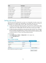
Verifying the configuration
•
Client 1 and Client 2 access the WLAN through an SSID named
service1
.
•
Check that traffic from Client 1 is rate limited to around 128 kbps, so is traffic from Client 2.
Dynamic rate limiting configuration example
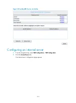
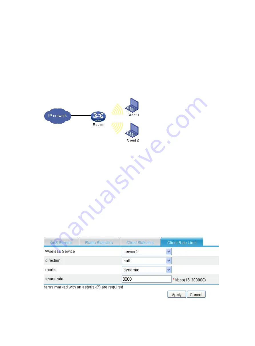
Network requirements
As shown in
, clients access the WLAN through a SSID named
service2
. Configure all clients
to share 8000 kbps of bandwidth in any direction.
Figure 128
Network diagram
Configuration procedure
1.
Configure the wireless service:
For the configuration procedure, see "
Wireless access service configuration examples
." You can
strictly follow the related configuration example to configure the wireless service.
2.
Configure dynamic rate limiting:
a.
Select
Interface Setup
>
Wireless
>
Wireless QoS
from the navigation tree.
b.
Click
Client Rate Limit.
c.
Click
Add
.
d.
On the page that appears, select
service2
from the
Wireless Service
list, select
both
from the
direction
list, select
dynamic
from the
mode
list, enter
8000
in the
share rate
field, and click
Apply
.
Figure 129
Configuring dynamic rate limiting
Summary of Contents for MSR SERIES
Page 17: ...xv Documents 835 Websites 835 Conventions 836 Index 838 ...
Page 20: ...3 Figure 3 Initial page of the Web interface ...
Page 42: ...25 Figure 13 Firefox Web browser setting ...
Page 59: ...42 Figure 27 Checking the basic service configuration ...
Page 73: ...56 Figure 35 Sample interface statistics ...
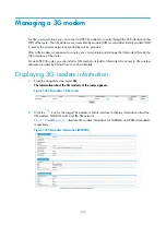
Page 156: ...139 Figure 139 Rebooting the 3G modem ...
Page 168: ...151 Figure 152 Configuring Web server 2 ...
Page 174: ...157 Figure 158 Configure the URL filtering function ...
Page 242: ...225 Figure 233 Enabling the DHCP client on interface Ethernet 0 1 ...
Page 247: ...230 Figure 236 The page for configuring an advanced IPv4 ACL ...
Page 255: ...238 Figure 241 Advanced limit setting ...
Page 298: ...281 e Click Apply 2 Configure Router B in the same way Router A is configured ...
Page 400: ...383 Figure 387 Verifying the configuration ...
Page 405: ...388 ...
Page 523: ...506 Figure 530 Ping configuration page ...
Page 775: ...758 Figure 785 Configuring a jump node ...


