


301
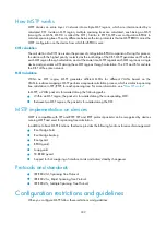
Figure 312
The STP algorithm
1.
State initialization of each device.
Table 139
Initial state of each device
Device Port
name
BPDU of port
Device A
AP1
{0, 0, 0, AP1}
AP2
{0, 0, 0, AP2}
Device B
BP1
{1, 0, 1, BP1}
BP2
{1, 0, 1, BP2}
Device C
CP1
{2, 0, 2, CP1}
CP2
{2, 0, 2, CP2}
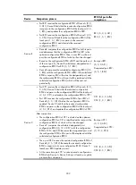
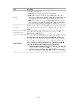
2.
BPDU comparisons on each device.
Table 140
Comparison process and result on each device
Device Comparison
process
BPDU of port after
comparison
Device A
•
Port AP1 receives the configuration BPDU of Device B {1, 0,
1, BP1}. Device A finds that the configuration BPDU of the
local port {0, 0, 0, AP1} is superior to the received
configuration BPDU, and discards the received
configuration BPDU.
•
Port AP2 receives the configuration BPDU of Device C {2, 0,
2, CP1}. Device A finds that the BPDU of the local port {0, 0,
0, AP2} is superior to the received configuration BPDU, and
discards the received configuration BPDU.
•
Device A finds that both the root bridge and designated
bridge in the configuration BPDUs of all its ports are itself, so
it assumes itself to be the root bridge. It does not make any
change to the configuration BPDU of each port, and starts
sending out configuration BPDUs periodically.
AP1: {0, 0, 0, AP1}
AP2: {0, 0, 0, AP2}
Summary of Contents for MSR SERIES
Page 17: ...xv Documents 835 Websites 835 Conventions 836 Index 838 ...
Page 20: ...3 Figure 3 Initial page of the Web interface ...
Page 42: ...25 Figure 13 Firefox Web browser setting ...
Page 59: ...42 Figure 27 Checking the basic service configuration ...
Page 73: ...56 Figure 35 Sample interface statistics ...
Page 156: ...139 Figure 139 Rebooting the 3G modem ...
Page 168: ...151 Figure 152 Configuring Web server 2 ...
Page 174: ...157 Figure 158 Configure the URL filtering function ...
Page 242: ...225 Figure 233 Enabling the DHCP client on interface Ethernet 0 1 ...
Page 247: ...230 Figure 236 The page for configuring an advanced IPv4 ACL ...
Page 255: ...238 Figure 241 Advanced limit setting ...
Page 298: ...281 e Click Apply 2 Configure Router B in the same way Router A is configured ...
Page 400: ...383 Figure 387 Verifying the configuration ...
Page 405: ...388 ...
Page 523: ...506 Figure 530 Ping configuration page ...
Page 775: ...758 Figure 785 Configuring a jump node ...


