


370
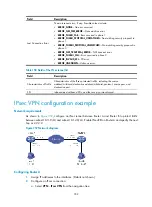
Item Description
End IP
The number of addresses between the start IP address and end IP address
must not exceed 1024. If you specify only the start IP address, the IP address
pool will contain only one IP address, namely, the start IP address.
Displaying L2TP tunnel information
1.
Select
VPN
>
L2TP
>
Tunnel Info
from the navigation tree to enter the L2TP tunnel information page.
Figure 367
L2TP tunnel information
2.
View the L2TP tunnel information.
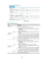
Table 162
Field description
Field Description
Local Tunnel ID
Local ID of the tunnel.
Peer Tunnel ID
Peer ID of the tunnel.
Peer Tunnel Port
Peer port of the tunnel.
Peer Tunnel IP
Peer IP address of the tunnel.
Session Count
Number of sessions on the tunnel.
Peer Tunnel Name
Peer name of the tunnel.
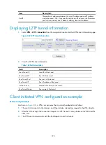
Client-initiated VPN configuration example
Network requirements
As shown in
, a VPN user accesses the corporate headquarters as follows:
1.
The user first connects to the Internet, and then initiates a tunneling request to the LNS directly.
2.
After the LNS accepts the connection request, an L2TP tunnel is set up between the LNS and the
VPN user.
3.
The VPN user communicates with the headquarters over the tunnel.
Summary of Contents for MSR SERIES
Page 17: ...xv Documents 835 Websites 835 Conventions 836 Index 838 ...
Page 20: ...3 Figure 3 Initial page of the Web interface ...
Page 42: ...25 Figure 13 Firefox Web browser setting ...
Page 59: ...42 Figure 27 Checking the basic service configuration ...
Page 73: ...56 Figure 35 Sample interface statistics ...
Page 156: ...139 Figure 139 Rebooting the 3G modem ...
Page 168: ...151 Figure 152 Configuring Web server 2 ...
Page 174: ...157 Figure 158 Configure the URL filtering function ...
Page 242: ...225 Figure 233 Enabling the DHCP client on interface Ethernet 0 1 ...
Page 247: ...230 Figure 236 The page for configuring an advanced IPv4 ACL ...
Page 255: ...238 Figure 241 Advanced limit setting ...
Page 298: ...281 e Click Apply 2 Configure Router B in the same way Router A is configured ...
Page 400: ...383 Figure 387 Verifying the configuration ...
Page 405: ...388 ...
Page 523: ...506 Figure 530 Ping configuration page ...
Page 775: ...758 Figure 785 Configuring a jump node ...


