


361
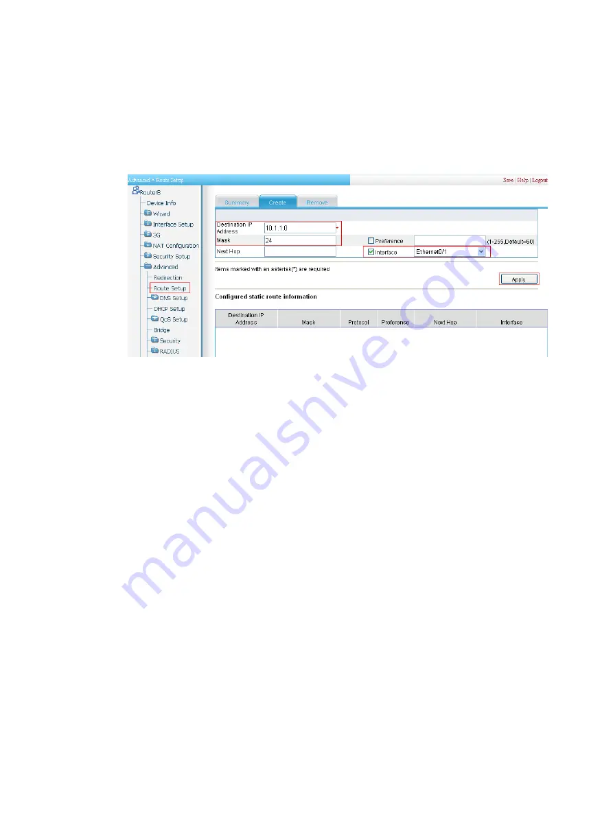
c.
Enter
10.1.1.0
as the destination IP address.
d.
Enter
24
as the mask.
e.
Select
Interface
and then select
Ethernet0/1
as the interface.
f.
Click
Apply
.
Figure 361
Configuring a static route to Host A
3.
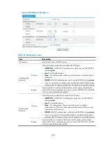
Configure an IPsec connection.
a.
Select
VPN
>
IPsec VPN
from the navigation tree.
b.
Click
Add
to enter the IPsec connection configuration page (see
).
c.
Enter
map1
as the IPsec connection name.
d.
Select interface
Ethernet0/1
.
e.
Enter
2.2.2.1
as the remote gateway IP address.
f.
Select the
Pre-Shared-Key
box, and then enter
abcde
in both the
Key
and
Confirm Key
fields.
g.
In the
Selector
area, select the selector type
Characteristics of Traffic
.
h.
Specify 10.1.2.0/0.0.0.255 as the source address/wildcard. Specify 10.1.1.0/0.0.0.255
as the destination address/wildcard.
i.
Click
Apply
.
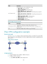
Verifying the configuration
After you complete the configuration, packets to be exchanged between subnet 10.1.1.0/24 and subnet
10.1.2.0/24 triggers the negotiation of SAs by IKE. After IKE negotiation succeeds and the IPsec SAs are
established, a static route to subnet 10.1.2.0/24 through 2.2.2.2 is added to the routing table on Device
A, and traffic between subnet 10.1.1.0/24 and subnet 10.1.2.0/24 is protected by IPsec.
Configuration guidelines
When you configure IPsec, follow these guidelines:
•
Typically, IKE uses UDP port 500 for communication, and AH and ESP use the protocol numbers 51
and 50 respectively. Make sure flows of these protocols are not denied on the interfaces with IKE or
IPsec configured.
Summary of Contents for MSR SERIES
Page 17: ...xv Documents 835 Websites 835 Conventions 836 Index 838 ...
Page 20: ...3 Figure 3 Initial page of the Web interface ...
Page 42: ...25 Figure 13 Firefox Web browser setting ...
Page 59: ...42 Figure 27 Checking the basic service configuration ...
Page 73: ...56 Figure 35 Sample interface statistics ...
Page 156: ...139 Figure 139 Rebooting the 3G modem ...
Page 168: ...151 Figure 152 Configuring Web server 2 ...
Page 174: ...157 Figure 158 Configure the URL filtering function ...
Page 242: ...225 Figure 233 Enabling the DHCP client on interface Ethernet 0 1 ...
Page 247: ...230 Figure 236 The page for configuring an advanced IPv4 ACL ...
Page 255: ...238 Figure 241 Advanced limit setting ...
Page 298: ...281 e Click Apply 2 Configure Router B in the same way Router A is configured ...
Page 400: ...383 Figure 387 Verifying the configuration ...
Page 405: ...388 ...
Page 523: ...506 Figure 530 Ping configuration page ...
Page 775: ...758 Figure 785 Configuring a jump node ...


