


167
•
Select
Enable Attack Defense Policy
.
•
Select
Enable Land Attack Detection
,
Enable Smurf Attack Detection
,
Enable Scanning Attack
Detection
, and
Add Source IP Address to the Blacklist
. Clear all other options.
•
Click
Apply
.
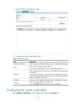
Verifying the configuration
•
Select
Security Setup
>
Attack Defend
>
Blacklist
. Host D and Host C are in the blacklist.
•
Router drops all packets from Host D unless you remove Host D from the blacklist.
•
Router drops packets from Host C within 50 minutes. Then, Router forwards packets from Host C
correctly.
•
Upon detecting the scanning attack, Router outputs an alarm log and adds the IP address of the
attacker to the blacklist. You can view the added blacklist entry by selecting
Security Setup
>
Attack
Defend
>
Blacklist
.
•
Upon detecting the Land or Smurf attack, Router outputs an alarm log and drops the attack packet.
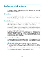
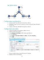
For MSR20/30/50/93X/1000 routers
Network requirements
As shown in
, internal users Host A, Host B, and Host C access the Internet through Router. The
network security requirements are as follows:
•
Router always drops packets from Host D, an attacker.
•
Router denies packets from Host C for 50 minutes for temporary access control of Host C.
•
Router provides scanning attack protection and automatically adds detected attackers to the
blacklist on interface Ethernet 0/2, the interface connecting the Internet.
•
Router provides Land attack protection and Smurf attack protection on Ethernet 0/2.
Figure 169
Network diagram
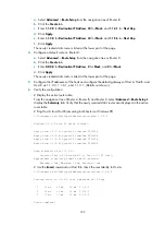
Configuration procedure
# Configure IP addresses for the interfaces. (Details not shown.)
# Enable the blacklist function.
•
Select
Security Setup
>
Attack Defend
>
Blacklist
from the navigation tree, and then perform the
following configurations, as shown in
.
Summary of Contents for MSR SERIES
Page 17: ...xv Documents 835 Websites 835 Conventions 836 Index 838 ...
Page 20: ...3 Figure 3 Initial page of the Web interface ...
Page 42: ...25 Figure 13 Firefox Web browser setting ...
Page 59: ...42 Figure 27 Checking the basic service configuration ...
Page 73: ...56 Figure 35 Sample interface statistics ...
Page 156: ...139 Figure 139 Rebooting the 3G modem ...
Page 168: ...151 Figure 152 Configuring Web server 2 ...
Page 174: ...157 Figure 158 Configure the URL filtering function ...
Page 242: ...225 Figure 233 Enabling the DHCP client on interface Ethernet 0 1 ...
Page 247: ...230 Figure 236 The page for configuring an advanced IPv4 ACL ...
Page 255: ...238 Figure 241 Advanced limit setting ...
Page 298: ...281 e Click Apply 2 Configure Router B in the same way Router A is configured ...
Page 400: ...383 Figure 387 Verifying the configuration ...
Page 405: ...388 ...
Page 523: ...506 Figure 530 Ping configuration page ...
Page 775: ...758 Figure 785 Configuring a jump node ...


