


693
Item Description
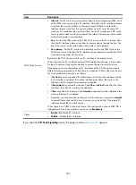
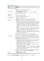
Ignore the Sending-Complete
Information Element in Setup
Messages
•
Enable for outgoing direction
—Configure the ISDN protocol to send Setup
messages without the Sending-Complete Information Element when
placing a call.
•
Enable for incoming direction
—Configure the ISDN protocol to ignore the
Sending-Complete Information Element in Setup messages when receiving
a call.
•
Enable for bidirectional directions
—Configure the ISDN protocol to ignore
the Sending-Complete Information Element in Setup messages when
receiving a call, and to send Setup messages without the
Sending-Complete Information Element when placing a call.
•
Disable (default)
—Configure ISDN not to ignore the Sending-Complete
Information Element in Setup messages. During data exchange between
the device and an ISDN switch, for an incoming call, if a Setup message
does not contain the Sending-Complete Information Element, the number is
not received completely. For an outgoing call, a Setup message containing
the Sending-Complete Information Element indicates that the number is
sent completely.
ISDN Sliding Window Size
Set the sliding window size on an ISDN BRI interface.
ISDN T302 Timer Duration
Configure the duration of the ISDN protocol Layer 3 timer T302.
ISDN Call Reference Length
Set the length of the call reference used when a call is placed on an ISDN
interface.
The call reference is equal to the sequence number that the protocol assigns to
each call. It is 1 or 2 bytes in length and can be used cyclically.
When the device receives a call from a remote device, it can automatically
identify the length of the call reference. However, some devices on the
network do not have this capability. In the event that the device is required to
place calls to such a device connected to it, you must configure the device to
use the same call reference length configured on the connected device.
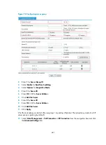
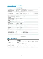
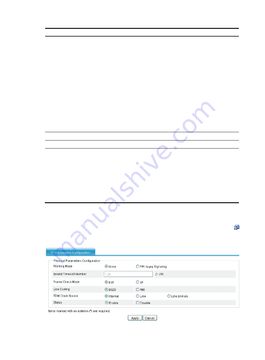
Configuring VT1 line
Select
Voice Management
>
Digital Link Management
from the navigation tree, and then click the
icon of the VT1 line to be configured to access the T1 parameters configuration page.
Figure 719
T1 parameters configuration page (1)
Summary of Contents for MSR SERIES
Page 17: ...xv Documents 835 Websites 835 Conventions 836 Index 838 ...
Page 20: ...3 Figure 3 Initial page of the Web interface ...
Page 42: ...25 Figure 13 Firefox Web browser setting ...
Page 59: ...42 Figure 27 Checking the basic service configuration ...
Page 73: ...56 Figure 35 Sample interface statistics ...
Page 156: ...139 Figure 139 Rebooting the 3G modem ...
Page 168: ...151 Figure 152 Configuring Web server 2 ...
Page 174: ...157 Figure 158 Configure the URL filtering function ...
Page 242: ...225 Figure 233 Enabling the DHCP client on interface Ethernet 0 1 ...
Page 247: ...230 Figure 236 The page for configuring an advanced IPv4 ACL ...
Page 255: ...238 Figure 241 Advanced limit setting ...
Page 298: ...281 e Click Apply 2 Configure Router B in the same way Router A is configured ...
Page 400: ...383 Figure 387 Verifying the configuration ...
Page 405: ...388 ...
Page 523: ...506 Figure 530 Ping configuration page ...
Page 775: ...758 Figure 785 Configuring a jump node ...


