


826
SIP UA states
The following pages show SIP UA states:
•
TCP Connection Information
page—Displays information about all TCP-based call connections.
•
TLS
Connection Information
page—Displays information about all TLS-based call connections.
•
Number Register Status
page—Displays number register information when you use SIP servers to
manage SIP calls.
•
Number Subscriber Status
pages—Displays the subscription status information of MWI when MWI
is in use.
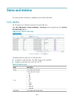
Displaying TCP connection information
Select
Voice Management
>
Sates and Statistics
>
SIP UA States
from the navigation tree. The
TCP
Connection Information
page appears.
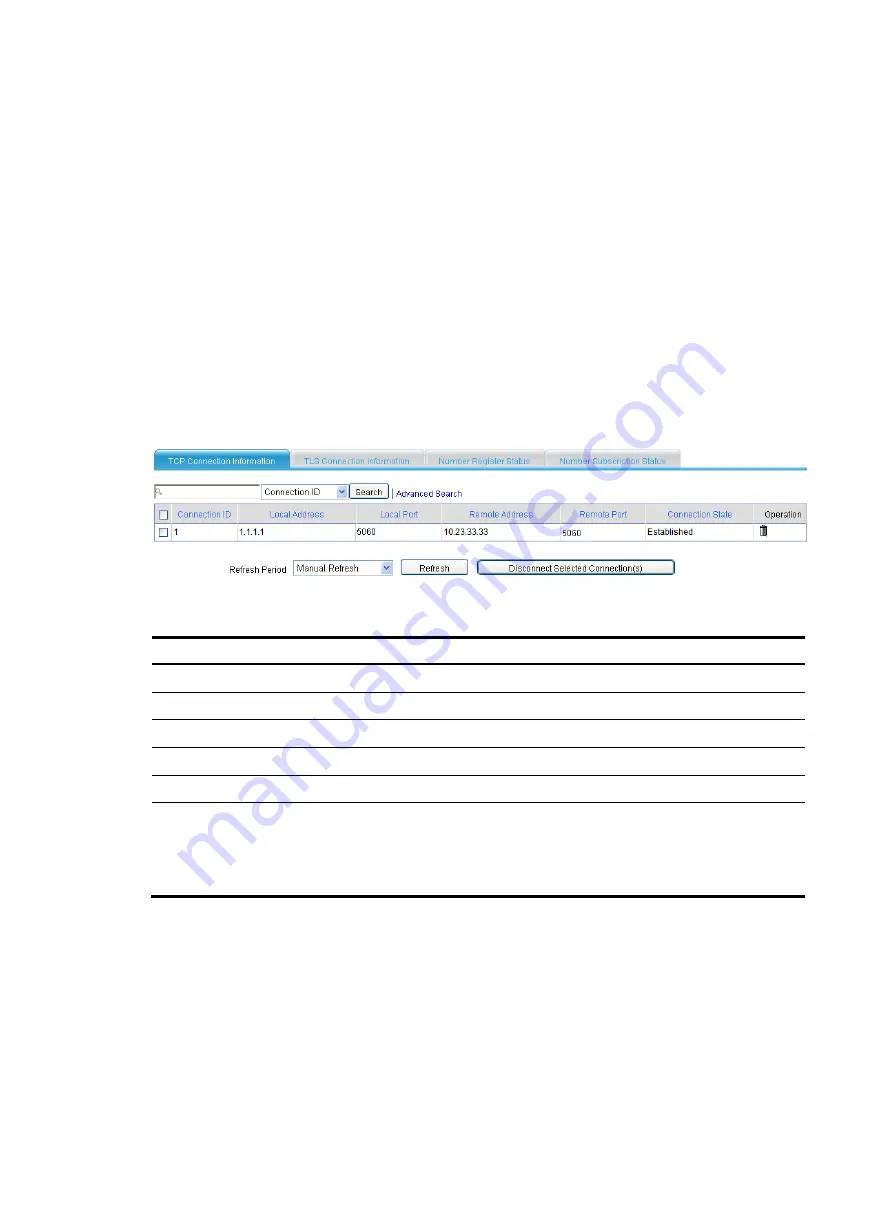
Figure 862
TCP connection information
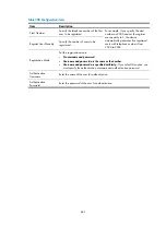
Table 311
Field description
Field Description
Connection ID
Call connection ID, automatically generated by the system.
Local Address
IP address of the calling party.
Local Port
Port number of the calling party.
Remote Address
IP address of the called party.
Remote Port
Port number of the called party.
Connection State
Connection state:
•
Idle.
•
Connecting.
•
Established.
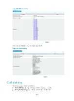
Displaying TLS connection information
Select
Voice Management
>
Sates and Statistics
>
SIP UA States
from the navigation tree. The
TLS
Connection Information
page appears.
Summary of Contents for MSR SERIES
Page 17: ...xv Documents 835 Websites 835 Conventions 836 Index 838 ...
Page 20: ...3 Figure 3 Initial page of the Web interface ...
Page 42: ...25 Figure 13 Firefox Web browser setting ...
Page 59: ...42 Figure 27 Checking the basic service configuration ...
Page 73: ...56 Figure 35 Sample interface statistics ...
Page 156: ...139 Figure 139 Rebooting the 3G modem ...
Page 168: ...151 Figure 152 Configuring Web server 2 ...
Page 174: ...157 Figure 158 Configure the URL filtering function ...
Page 242: ...225 Figure 233 Enabling the DHCP client on interface Ethernet 0 1 ...
Page 247: ...230 Figure 236 The page for configuring an advanced IPv4 ACL ...
Page 255: ...238 Figure 241 Advanced limit setting ...
Page 298: ...281 e Click Apply 2 Configure Router B in the same way Router A is configured ...
Page 400: ...383 Figure 387 Verifying the configuration ...
Page 405: ...388 ...
Page 523: ...506 Figure 530 Ping configuration page ...
Page 775: ...758 Figure 785 Configuring a jump node ...


