


306
•
They have the same region name.
•
They have the same VLAN-to-instance mapping configuration.
•
They have the same MSTP revision level configuration.
•
They are physically linked with one another.
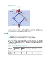
For example, all the devices in region A0 in
have the same MST region configuration.
•
The same region name.
•
The same VLAN-to-instance mapping configuration (VLAN 1 is mapped to MSTI 1, VLAN 2 to MSTI
2, and the rest to the common and internal spanning tree (CIST or MSTI 0).
•
The same MSTP revision level (not shown in the figure).
Multiple MST regions can exist in a switched network. You can assign multiple devices to the same MST
region.
VLAN-to-instance mapping table
As an attribute of an MST region, the VLAN-to-instance mapping table describes the mapping
relationships between VLANs and MSTIs. In
, for example, the VLAN-to-instance mapping
table of region A0 is: VLAN 1 is mapped to MSTI 1, VLAN 2 to MSTI 2, and the rest to CIST. MSTP
achieves load balancing by means of the VLAN-to-instance mapping table.
IST
An internal spanning tree (IST) is a spanning tree that runs in an MST region.
ISTs in all MST regions and the common spanning tree (CST) jointly constitute the common and internal
spanning tree (CIST) of the entire network. An IST is a section of the CIST in an MST region.
In
, for example, the CIST has a section in each MST region, and this section is the IST in the
respective MST region.
CST
The CST is a single spanning tree that connects all MST regions in a switched network. If you regard each
MST region as a "device," the CST is a spanning tree calculated by these devices through STP or RSTP.
CSTs are indicated by red lines in
.
CIST
Jointly constituted by ISTs and the CST, the CIST is a single spanning tree that connects all devices in a
switched network.
In
, for example, the ISTs in all MST regions plus the inter-region CST constitute the CIST of the
entire network.
MSTI
Multiple spanning trees can be generated in an MST region through MSTP, one spanning tree being
independent of another. Each spanning tree is called a multiple spanning tree instance (MSTI).
In
, for example, multiple MSTIs can exist in each MST region, each MSTI corresponding to the
specified VLANs.
Regional root bridge
The root bridge of the IST or an MSTI within an MST region is the regional root bridge of the IST or the
MSTI. Based on the topology, different spanning trees in an MST region might have different regional
roots.
Summary of Contents for MSR SERIES
Page 17: ...xv Documents 835 Websites 835 Conventions 836 Index 838 ...
Page 20: ...3 Figure 3 Initial page of the Web interface ...
Page 42: ...25 Figure 13 Firefox Web browser setting ...
Page 59: ...42 Figure 27 Checking the basic service configuration ...
Page 73: ...56 Figure 35 Sample interface statistics ...
Page 156: ...139 Figure 139 Rebooting the 3G modem ...
Page 168: ...151 Figure 152 Configuring Web server 2 ...
Page 174: ...157 Figure 158 Configure the URL filtering function ...
Page 242: ...225 Figure 233 Enabling the DHCP client on interface Ethernet 0 1 ...
Page 247: ...230 Figure 236 The page for configuring an advanced IPv4 ACL ...
Page 255: ...238 Figure 241 Advanced limit setting ...
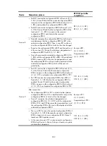
Page 298: ...281 e Click Apply 2 Configure Router B in the same way Router A is configured ...
Page 400: ...383 Figure 387 Verifying the configuration ...
Page 405: ...388 ...
Page 523: ...506 Figure 530 Ping configuration page ...
Page 775: ...758 Figure 785 Configuring a jump node ...


