


679
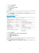
8.
Enter
2000
for
Destination Number
.
9.
Select
SIP
for
Call Route Type
.
10.
Select
Proxy Server
for
SIP Routing
.
11.
Click
Apply
.
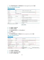
# Configure the IPv4 address of the registrar as 10.1.1.2 and enable the registrar.
12.
Select
Voice Management
>
Call Connection
>
SIP Connection
from the navigation tree and click
the
Connection Properties
tab.
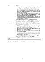
Figure 710
Configuring connection properties
13.
Select
Enable
for
Register State
.
14.
Enter
10.1.1.2
for
Main Registrar Address
.
15.
Click
Apply
.
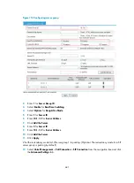
Verifying the configuration
1.
On the SIP trunk device, display SIP trunk account information.
Select
Voice Management
>
States and Statistics
>
SIP Trunk Account States
from the navigation
tree. You can see that the private network account 2000 has registered with the server at
10.1.1.2.
2.
All calls between the private network and public network are made through the SIP trunk device.
On the SIP trunk device, you can see in
Voice Management
>
States and Statistics
>
Call Statistics
that all calls between the private network and public network are made through the SIP trunk
device.
3.
On the SIP server of the carrier, you can view only the interface address of the SIP trunk device,
which means that the SIP trunk device can filter the information of the enterprise private network
users.
Configuring a SIP server group with multiple member servers
Network requirements
The enterprise private network has a SIP trunk device. Router A is a private network device, and Router
B is a public network device. Configure a SIP server group with multiple member servers so that all calls
between the private network and public network are made through the SIP trunk device. The carrier is
required to provide multiple servers to ensure call reliability.
Summary of Contents for MSR SERIES
Page 17: ...xv Documents 835 Websites 835 Conventions 836 Index 838 ...
Page 20: ...3 Figure 3 Initial page of the Web interface ...
Page 42: ...25 Figure 13 Firefox Web browser setting ...
Page 59: ...42 Figure 27 Checking the basic service configuration ...
Page 73: ...56 Figure 35 Sample interface statistics ...
Page 156: ...139 Figure 139 Rebooting the 3G modem ...
Page 168: ...151 Figure 152 Configuring Web server 2 ...
Page 174: ...157 Figure 158 Configure the URL filtering function ...
Page 242: ...225 Figure 233 Enabling the DHCP client on interface Ethernet 0 1 ...
Page 247: ...230 Figure 236 The page for configuring an advanced IPv4 ACL ...
Page 255: ...238 Figure 241 Advanced limit setting ...
Page 298: ...281 e Click Apply 2 Configure Router B in the same way Router A is configured ...
Page 400: ...383 Figure 387 Verifying the configuration ...
Page 405: ...388 ...
Page 523: ...506 Figure 530 Ping configuration page ...
Page 775: ...758 Figure 785 Configuring a jump node ...


