


732
Figure 753
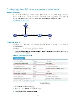
Configuring a call-out route
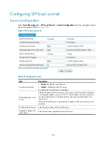
Table 281
Configuration items
Item Description
ID
Enter the ID of the call-out route.
Destination Number
Prefix
Enter the destination number prefix and length. Suppose the destination number
prefix is 4100, and the number length is 6. This configuration matches destination
numbers that are 6-digit long and start with 4100.
A dot can be used after a number to represent a character. This configuration does
not support other characters.
Number length
Destination IP address
Enter the destination IP address and port number.
Port Number
Area Prefix
Enter the area prefix added before the calling numbers of outgoing calls.
Area prefix
When the local SIP server is connected to the extranet, external users can originate calls to internal users
registered with the local SIP server. For calls from external users to internal users, the local SIP server
removes the configured area prefix from each called number to converts it to an internal short number.
For example, if an external user dials number 01050009999, the local SIP server checks whether any
area prefix matches the called number. If the area prefix 0105000 is available, the local SIP server
removes the prefix 0105000 from the called number and sends the call to 9999.
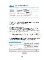
Select
Voice Management
>
SIP Local Survival
>
Area Prefix
from the navigation tree to access the page
.
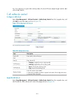
Figure 754
Configuring a call-in number prefix
Enter the call-in number prefix, and click
Add a Prefix
.
Summary of Contents for MSR SERIES
Page 17: ...xv Documents 835 Websites 835 Conventions 836 Index 838 ...
Page 20: ...3 Figure 3 Initial page of the Web interface ...
Page 42: ...25 Figure 13 Firefox Web browser setting ...
Page 59: ...42 Figure 27 Checking the basic service configuration ...
Page 73: ...56 Figure 35 Sample interface statistics ...
Page 156: ...139 Figure 139 Rebooting the 3G modem ...
Page 168: ...151 Figure 152 Configuring Web server 2 ...
Page 174: ...157 Figure 158 Configure the URL filtering function ...
Page 242: ...225 Figure 233 Enabling the DHCP client on interface Ethernet 0 1 ...
Page 247: ...230 Figure 236 The page for configuring an advanced IPv4 ACL ...
Page 255: ...238 Figure 241 Advanced limit setting ...
Page 298: ...281 e Click Apply 2 Configure Router B in the same way Router A is configured ...
Page 400: ...383 Figure 387 Verifying the configuration ...
Page 405: ...388 ...
Page 523: ...506 Figure 530 Ping configuration page ...
Page 775: ...758 Figure 785 Configuring a jump node ...


