


747
Verifying the configuration
•
Select
Voice Management
>
States and Statistics
>
Local Survival Service States
from the
navigation tree. You can find that number 5000 has been registered with the local SIP server on
Router C.
•
Place a call from phone 55661000 to phone 88995000. The local SIP server on Router C removes
the area prefix 8899 from the called number, and alerts internal phone 5000. Pick up phone 5000.
The call is established.
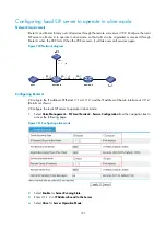
Configuring a call-out route
Network requirements
The internal numbers of a company are four-digit long and the area prefix is 8899. External phone
55665000 attached to Router B is not registered with the local SIP server on Router C; internal phone
1000 attached to Router A is already registered with Router C. When a user in the company dials the
external number, the local SIP server will route the call according to the configured call-out route and add
area prefix 8899 to the calling number.
Figure 775
Network diagram
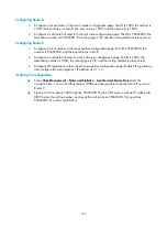
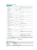
Configuring the local SIP server on Router C
# Configure the local SIP server to operate in alone mode.
1.
Select
Voice Management
>
SIP Local Survival
>
Service Configuration
from the navigation tree to
access the page for configuring services.
Figure 776
Configuring alone mode
2.
Select
Enable
for
Server Running State
.
3.
Enter 2.1.1.2 in
IP Address Bound to the Server
.
Summary of Contents for MSR SERIES
Page 17: ...xv Documents 835 Websites 835 Conventions 836 Index 838 ...
Page 20: ...3 Figure 3 Initial page of the Web interface ...
Page 42: ...25 Figure 13 Firefox Web browser setting ...
Page 59: ...42 Figure 27 Checking the basic service configuration ...
Page 73: ...56 Figure 35 Sample interface statistics ...
Page 156: ...139 Figure 139 Rebooting the 3G modem ...
Page 168: ...151 Figure 152 Configuring Web server 2 ...
Page 174: ...157 Figure 158 Configure the URL filtering function ...
Page 242: ...225 Figure 233 Enabling the DHCP client on interface Ethernet 0 1 ...
Page 247: ...230 Figure 236 The page for configuring an advanced IPv4 ACL ...
Page 255: ...238 Figure 241 Advanced limit setting ...
Page 298: ...281 e Click Apply 2 Configure Router B in the same way Router A is configured ...
Page 400: ...383 Figure 387 Verifying the configuration ...
Page 405: ...388 ...
Page 523: ...506 Figure 530 Ping configuration page ...
Page 775: ...758 Figure 785 Configuring a jump node ...