


169
•
Enter IP address
192.168.1.5
, the IP address of Host C.
•
Select
Hold Time
and set the hold time of this blacklist entry to 50 minutes.
•
Click
Apply
.
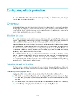
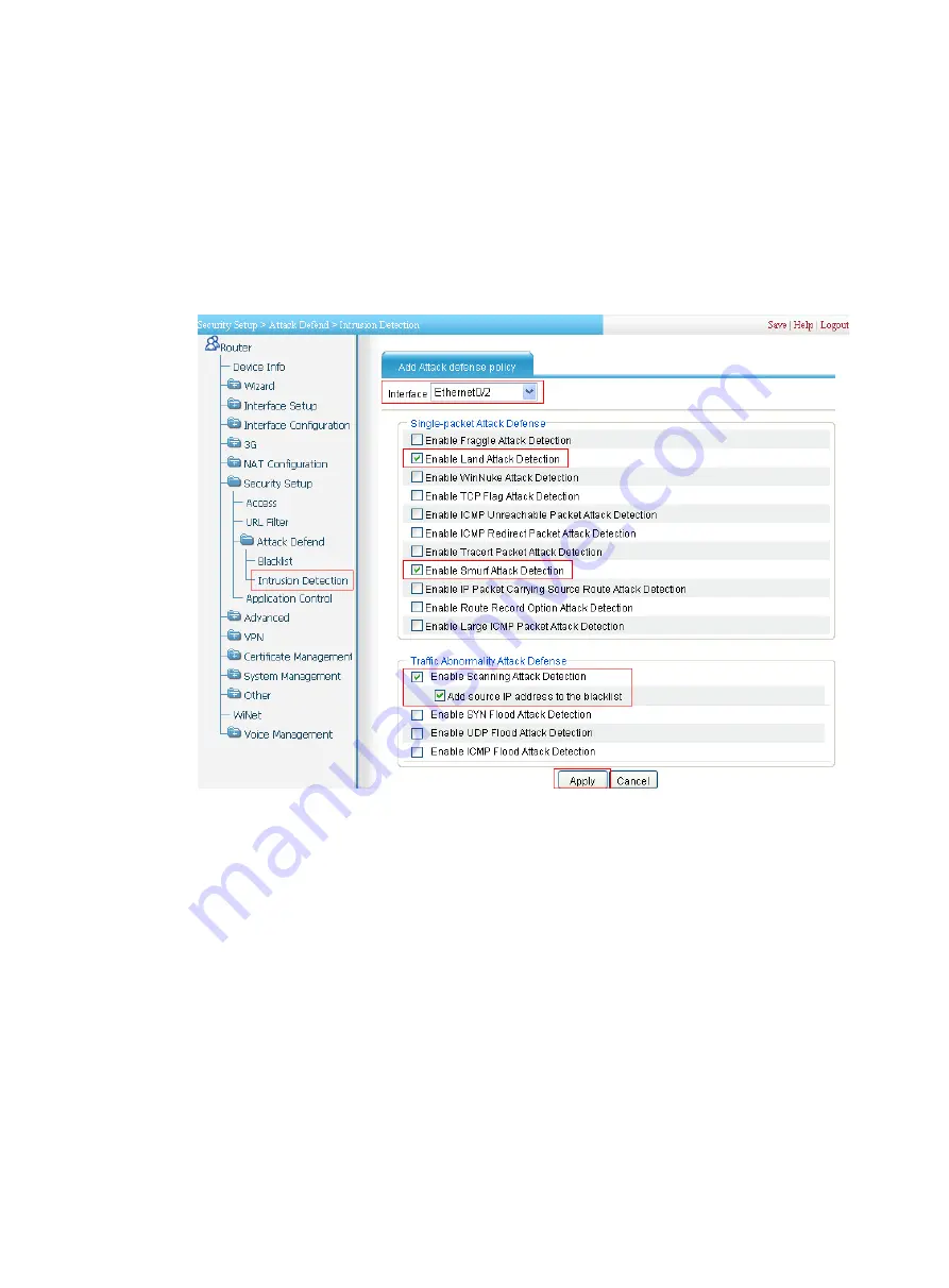
# Configure intrusion detection on Ethernet 0/2: Enable scanning attack protection, and enable blacklist
function for it; enable Land attack protection and Smurf attack protection.
•
Select
Security Setup
>
Attack Defend
>
Intrusion Detection
from the navigation tree. Click
Add
and
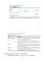
then perform the following configurations, as shown in
Figure 173
Configuring intrusion detection
•
Select interface
Ethernet0/2
.
•
Select
Enable Attack Defense Policy
.
•
Select
Enable Land Attack Detection
,
Enable Smurf Attack Detection
,
Enable Scanning Attack
Detection
, and
Add Source IP Address to the Blacklist
. Clear all other options.
•
Click
Apply
.
Verifying the configuration
•
Select
Security Setup
>
Attack Defend
>
Blacklist
. Host D and Host C are in the blacklist.
•
Router drops all packets from Host D unless you remove Host D from the blacklist.
•
Router drops packets from Host C within 50 minutes. Then, Router forwards packets from Host C
correctly.
•
Upon detecting the scanning attack on Ethernet 0/2, Router outputs an alarm log and adds the IP
address of the attacker to the blacklist. You can view the added blacklist entry by selecting
Security
Setup
>
Attack Defend
>
Blacklist
.
Summary of Contents for MSR SERIES
Page 17: ...xv Documents 835 Websites 835 Conventions 836 Index 838 ...
Page 20: ...3 Figure 3 Initial page of the Web interface ...
Page 42: ...25 Figure 13 Firefox Web browser setting ...
Page 59: ...42 Figure 27 Checking the basic service configuration ...
Page 73: ...56 Figure 35 Sample interface statistics ...
Page 156: ...139 Figure 139 Rebooting the 3G modem ...
Page 168: ...151 Figure 152 Configuring Web server 2 ...
Page 174: ...157 Figure 158 Configure the URL filtering function ...
Page 242: ...225 Figure 233 Enabling the DHCP client on interface Ethernet 0 1 ...
Page 247: ...230 Figure 236 The page for configuring an advanced IPv4 ACL ...
Page 255: ...238 Figure 241 Advanced limit setting ...
Page 298: ...281 e Click Apply 2 Configure Router B in the same way Router A is configured ...
Page 400: ...383 Figure 387 Verifying the configuration ...
Page 405: ...388 ...
Page 523: ...506 Figure 530 Ping configuration page ...
Page 775: ...758 Figure 785 Configuring a jump node ...


