


126
Field
Description
Uplink CAC packets
Number of uplink CAC packets.
Uplink CAC bytes
Number of uplink CAC bytes.
Downlink CAC packets
Number of downlink CAC packets.
Downlink CAC bytes
Number of downlink CAC bytes.
Downgrade packets
Number of downgraded packets.
Downgrade bytes
Number of downgraded bytes.
Discard packets
Number of dropped packets.
Discard bytes
Number of dropped bytes.
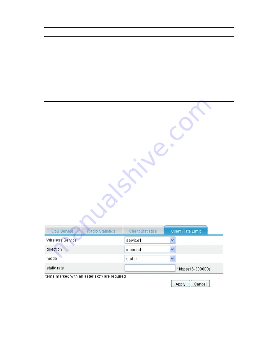
Setting rate limiting
The WLAN provides limited bandwidth for each device. As the bandwidth is shared by wireless clients
attached to the device, aggressive use of bandwidth by a client will affect other clients. To ensure fair use
of bandwidth, you can rate limit traffic of clients in either of the following two approaches:
•
Configure the total bandwidth shared by all clients in the same BSS. This is called dynamic mode.
The rate limit of a client is the configured total rate/the number of online clients. For example, if the
configure total rate is 10 Mbps and five clients are online, the rate of each client is 2 Mbps.
•
Configure the maximum bandwidth that can be used by each client in the BSS. This is called static
mode. For example, if the configured rate is 1 Mbps, the rate limit of each user online is 1 Mbps.
When the set rate limit multiplied by the number of access clients exceeds the available bandwidth
provided by the device, no clients can get the guaranteed bandwidth.
To set rate limiting:
1.
Select
Interface Setup
>
Wireless
>
Wireless QoS
from the navigation tree.
2.
Click the
Client Rate Limit
tab.
3.
Click
Add
.
Figure 121
Setting rate limiting
Summary of Contents for MSR SERIES
Page 17: ...xv Documents 835 Websites 835 Conventions 836 Index 838 ...
Page 20: ...3 Figure 3 Initial page of the Web interface ...
Page 42: ...25 Figure 13 Firefox Web browser setting ...
Page 59: ...42 Figure 27 Checking the basic service configuration ...
Page 73: ...56 Figure 35 Sample interface statistics ...
Page 156: ...139 Figure 139 Rebooting the 3G modem ...
Page 168: ...151 Figure 152 Configuring Web server 2 ...
Page 174: ...157 Figure 158 Configure the URL filtering function ...
Page 242: ...225 Figure 233 Enabling the DHCP client on interface Ethernet 0 1 ...
Page 247: ...230 Figure 236 The page for configuring an advanced IPv4 ACL ...
Page 255: ...238 Figure 241 Advanced limit setting ...
Page 298: ...281 e Click Apply 2 Configure Router B in the same way Router A is configured ...
Page 400: ...383 Figure 387 Verifying the configuration ...
Page 405: ...388 ...
Page 523: ...506 Figure 530 Ping configuration page ...
Page 775: ...758 Figure 785 Configuring a jump node ...


