


274
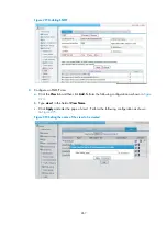
Figure 283
The bridge determines that Host B is also attached to interface 1
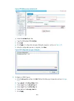
Finally, the bridge obtains all the MAC-interface mappings (assume that all hosts are in use), as shown
in
.
Figure 284
The final bridge table
Forwarding and filtering
The bridge makes data forwarding or filtering decisions based on the following scenarios:
•
When Host A sends an Ethernet frame to Host C, the bridge searches its bridge table and finds out
that Host C is attached to bridging interface 2, and forwards the Ethernet frame out of bridging
interface 2, as shown in
.
Host A
Host B
Host C
Host D
LAN segment 2
LAN segment 1
Bridge
Bridge interface 1
Bridge interface 2
00e0.fcbb. bbbb
00e0 .fcaa.aaaa
Source address
Destination address
00e 0.fcbb.bbbb
1
00e 0.fcaa.aaaa
1
MAC address
Interface
Bridge table
MAC address: 00e0.fcaa.aaaa
MAC address: 00e0.fccc.cccc
MAC address: 00e0.fcdd.dddd
MAC address: 00e0.fcbb.bbbb
MAC address: 00e0.fccc.cccc
Host A
Host B
Host C
Host D
LAN segment 2
LAN segment 1
Bridge interface 1
00e0.fcbb.bbbb
1
00e0.fccc.cccc
2
00e0.fcaa.aaaa
1
00e0.fcdd.dddd
2
MAC address
Interface
Bridge table
MAC address: 00e0.fcaa.aaaa
MAC address: 00e0.fcdd.dddd
MAC address: 00e0.fcbb.bbbb
Bridge interface 2
Bridge
Summary of Contents for MSR SERIES
Page 17: ...xv Documents 835 Websites 835 Conventions 836 Index 838 ...
Page 20: ...3 Figure 3 Initial page of the Web interface ...
Page 42: ...25 Figure 13 Firefox Web browser setting ...
Page 59: ...42 Figure 27 Checking the basic service configuration ...
Page 73: ...56 Figure 35 Sample interface statistics ...
Page 156: ...139 Figure 139 Rebooting the 3G modem ...
Page 168: ...151 Figure 152 Configuring Web server 2 ...
Page 174: ...157 Figure 158 Configure the URL filtering function ...
Page 242: ...225 Figure 233 Enabling the DHCP client on interface Ethernet 0 1 ...
Page 247: ...230 Figure 236 The page for configuring an advanced IPv4 ACL ...
Page 255: ...238 Figure 241 Advanced limit setting ...
Page 298: ...281 e Click Apply 2 Configure Router B in the same way Router A is configured ...
Page 400: ...383 Figure 387 Verifying the configuration ...
Page 405: ...388 ...
Page 523: ...506 Figure 530 Ping configuration page ...
Page 775: ...758 Figure 785 Configuring a jump node ...


