


780
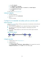
Figure 808
Network diagram
Configuration procedure
1.
Configure Router A: See
2.
Configure Router B:
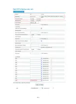
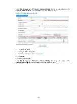
# Configure a local number in the local number configuration page.
The number ID is 500, the number is 500, and the bound line is line 1/0.
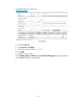
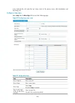
# Upload a g729r8 media resource file.
Select
Voice Management
>
IVR Services
>
Media Resources Management
from the navigation
tree to access the following page.
Figure 809
Uploading a g729r8 media resource file
a.
Enter 10001 for
Media Resource ID
.
b.
Enter welcome for
Rename Media Resource
.
c.
Click the
Browse
button of g729r8 codec to select the target file.
d.
Click
Apply
.
Use the same method to upload other g729r8 media resource files
timeout
,
input_error
, and
bye
.
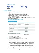
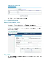
# Configure global error and timeout processing methods to achieve the following purposes:
If no number is dialed at Telephone A within the timeout time, Router B plays audio file
timeout.wav
. If number of timeouts reaches 4, Router B terminates the call.
If the subscriber dials a wrong number at Telephone A, Router B plays the audio file
input_error.wav
. If the number of input errors reaches 3, Router B terminates the call.
Select
Voice Management
>
IVR Services
>
Advanced Settings
from the navigation tree, and select
the
Global Key Policy
tab.
Summary of Contents for MSR SERIES
Page 17: ...xv Documents 835 Websites 835 Conventions 836 Index 838 ...
Page 20: ...3 Figure 3 Initial page of the Web interface ...
Page 42: ...25 Figure 13 Firefox Web browser setting ...
Page 59: ...42 Figure 27 Checking the basic service configuration ...
Page 73: ...56 Figure 35 Sample interface statistics ...
Page 156: ...139 Figure 139 Rebooting the 3G modem ...
Page 168: ...151 Figure 152 Configuring Web server 2 ...
Page 174: ...157 Figure 158 Configure the URL filtering function ...
Page 242: ...225 Figure 233 Enabling the DHCP client on interface Ethernet 0 1 ...
Page 247: ...230 Figure 236 The page for configuring an advanced IPv4 ACL ...
Page 255: ...238 Figure 241 Advanced limit setting ...
Page 298: ...281 e Click Apply 2 Configure Router B in the same way Router A is configured ...
Page 400: ...383 Figure 387 Verifying the configuration ...
Page 405: ...388 ...
Page 523: ...506 Figure 530 Ping configuration page ...
Page 775: ...758 Figure 785 Configuring a jump node ...


