background image

REAR 

REAR WHEEL 

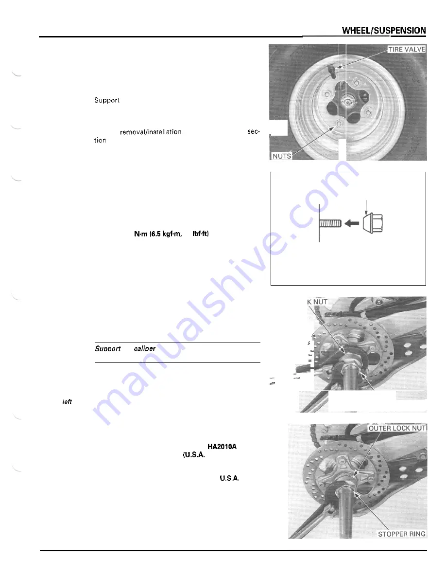
REMOVAL 

Loosen the wheel nuts. 

the vehicle with 

support block to  raise the 

rear wheels off the ground. 
Remove the nuts and wheel. 

For tire 

and  repair,  refer to 

12. 

INSTALLATION 

Install the tire onto the  hub with the tire valve facing 
out. 

Install the  wheel  nuts  with  the  tapered  side  facing 
inward and tighten them. 

TORQUE: 64 

47 

REAR AXLE 

REMOVAL 

TAPERED SIDE 

INNER 

LOC 

CAUTION: 

the 

so 

that 

it 

does not hang from the 

brake hose. 

Do 

n o t  twist or bend the brakehose. 

Remove the rear brake caliper (page 14-6). 

.- 

.- 

Thelocknuts 

has 

hand 

Loosen the  axle  inner  lock  nut while  holding the 

outer lock nut, using the special tools. 

threads 

OUTER 

LOCK 

NUT 

TOOLS 

Lock nut wrench, 

56 

mm 

07916 

HA20000 

or 

07916- 

only) 

07916 

1870101 or 

equivalent commercially 
available 

in 

Lock nut wrench, 

45 

mm 

Loosen the  outer  lock  nut  until the  stopper  ring can 
be removed, using same tool. 

Remove the stopper ring from the axle groove. 

13-3 

Summary of Contents for TRX400EX FOURTRAX 1999

Page 1: ......

Page 2: ......

Page 3: ......

Page 4: ...e molybdenum disulfide grease containing more than 3 molybdenum disulfide NLGl 2 or equivalent Example Molykote BR 2 plus manufactured by Dow Corning U S A Use molybdenum disulfide paste containing mo...

Page 5: ...EACH OF CHILDREN HOTCOMPONENTS Engine and exhaust system park become very hot and remain hot for some time after the engine is run Wear insulated gloves or wait until the engine and exhaust system hav...

Page 6: ...nuine HONDA or HONDA recommendedparts and lubricants or their equivalents Parts that don t meet HONDAs 2 Use the special tools designed for this product to avoid damage and incorrect assembly 3 Use on...

Page 7: ...e Identification Number VIN is located on the The engine serial number is stamped on the lower left of ENGiNE SERIALNUMBER I the crankcase I COLOR LABEL The carburetor identification number is stamped...

Page 8: ...ion system Oil pump type Cooling system Air filtration Engine dry weight SPECIFICATIONS 1 835 mm 72 2 in 1 150 mm 45 3 in 1 110 rnm 43 7 in 1 230 mm 48 4 in 810 mm 31 9 in 353 mm 13 9 in 110 mm 4 3 in...

Page 9: ...Starting system Charging system Regulatortrectifier Lighting system SPECIFICATIONS Piston valve 38 mm 1 5 in Multi plate wet Cable operating Constant mesh 5 speeds 2 826 23 65 2 533 15 38 2 916 12 35...

Page 10: ...ion SF or SG Viscosity SAE 1OW 40or 2OW 50 0 15 0 006 0 15 0 22 0 006 0 009 0 02 0 09 0 001 0 004 I ITEM SPECIFICATIONS 0 12 10 005 Main jet 148 Jet needle clip position Pilot screw opening Float leve...

Page 11: ...econd 0 015 0 050 0 0006 0 0020 0 12 0 005 0 20 0 70 0 008 0 028 Cylinder to piston clearance Connecting rod small end I D Connectino rod to Diston Din clearance Outer guide 0 015 0 050 0 0006 0 0020...

Page 12: ...RAL INFORMATION ITEM STANDARD SERVICE LIMIT rransmission rankshaft Runout 0 12 0 005 Big end side clearance Big end radial clearance 0 05 0 45 0 002 0 018 0 006 0 018 0 0002 0 0007 0 6 0 02 0 05 0 002...

Page 13: ...IMIT 4 0 0 16 27 kPa 0 275 kgf cm2 4 0 psi 23 kPa 0 235kgWcmz 3 4psi 3 1 kPa 10 315kaWcm2 4 6osil Axle runout Drive chain slack Shock absorber spring installed length 3 010 12 30 40 1 1 4 1 5 8 231 5...

Page 14: ...rk plug Standard DPR8Z NGK X24GPR U DENSO DPR9Z NGK X27GPR U DENSO For extended hiah weed ridina Bulbs Spark plug gap 0 6 0 7 mrn 0 024 0 028 in Neutral indicator I 12 v 3 4 w Ignition coil primary pe...

Page 15: ...e cap Valve adjusting lock nut Crankshaft hole cap Timing hole cap Engine oil drain bolt crankcase Engine oil drain bolt oil tank Engine oil strainer screen at oil tank Oil pipe joint flare nut ZYLIND...

Page 16: ...nut Steering shaft holder bolt 3EAR WHEELISUSPENSION Rear wheel nut Rear wheel hub nut Rear brake disc bolt Shock absorber mounting nut Shock link to swingarm nut Shock arm to frame nut Shock arm to...

Page 17: ...in Rear brakecaliper bracket pin Rear brakecaliper mounting bolt Rear brakecaliper parking brake base bolt nut Rear master cylinder reservoir hose joint screw LIGHTSISWITCHES DTHERS Headlight mounting...

Page 18: ...er set 15 mm bearing remover 15 mm remover shaft remover head slidingweight Needle bearing remover TOOL NUMBER 07401 0010000 07631 0010000 07724 0010100 07724 0050002 07725 0040000 07733 0020001 07741...

Page 19: ...Spherical bearing driver Ball joint remover TOOL NUMBER 07965 V M O O O O O 07965 VMOOlOO 07965 VM00200 07965 VM00300 07965 VMOOlOO 07984 2000001 07HMF HCOOlOO 07MAC SLOO200 REMARKS NOTE 2 NOTE 3 079...

Page 20: ...ut threads and seating surface Flywheel bolt threads and seating surface Transmission gear teeth Shift fork shaft Shift fork guide pins and inner surfaces Shift drum grooves Each bearing rotating area...

Page 21: ...reads and seating surfaces Rear shock absorber upper needle bearing Rear shock absorber dust seal lips LOCATION Engine oil Cable lubricant MATERIAL Multi purposegrease Front brake lever to masterpisto...

Page 22: ...ORMATION CABLE HARNESS ROUTING THROTTLE CABLE BRAKE LOCK CABLE BRAKE HOSE ANDLEBAR SWITCH WIRE CLUTCH CABLE OIL TANK BREATHER TUBE NEUTRAL INDICATOR CONNECTORS EADLIGHT CONNECTOR IGNITION SWITCH CONNE...

Page 23: ...GENERAL INFORMATION 1 19...

Page 24: ...GENERAL INFORMATION 1 20...

Page 25: ...GENERAL INFORMATION NEUTRAL SWITCH WlRF DIODE CARBURETOR DRAIN TUBE THROlTLE CABLE CARBURETOR AIR VENT TUBE I I FUEL TUBE 1 21...

Page 26: ...GENERAL INFORMATION MASTER CYLINDER RESERVOIR HOSE I 1 22...

Page 27: ...revent discharging crankcase emissions into the atmosphere Blow by gas is returned to the combustion chamber through the air cleaner and carburetor AIR CLEANER CONNECTINGTUBE CARBURETOR 1 AiRCLEANER C...

Page 28: ...GENERAL INFORMATION EMISSION CONTROL INFORMATION LABEL The Vehicle Emission Control Information Label is attached on the right side frame down tube VEHICLE EMISSION CONTROL INFORMATION LABEL 1 24...

Page 29: ...area or where gasoline is stored can cause a fire or explosion This section covers removal and installation of the body panels fuel tank and exhaust system Always replacethe gaskets when removing the...

Page 30: ...o the front mounting rubbers of the frame Push the seatlfender assembly forward and align the mounting bosses with the rear mounting rubbers then press down to lock it LOCK LEVER FENDER MOUNTING RUBBE...

Page 31: ...trim clips Release the side cover from the three tabs of the front fender by sliding it forward and remove the side cover Installation is in the reverse order of removal When installing the trim clips...

Page 32: ...otector Remove the clutch cable from the cable guide on the protector Release the trim clip by raising the center pin and remove it Remove the fuel tube from the protector rubber Remove the two mounti...

Page 33: ...socket bolts and washers and the footpeg Installation is in the reverse order of removal TORQUE Footpeg bracket bolt 42 Nm 14 3 k g f m 31 IbfW y WASHEWBOLT OUTER MUD GUARD STAY INNER MUD GUARD ST WA...

Page 34: ...joint gaskets Set the exhaust pipe flange as shown I GASKET I EXHAUST PIPE MOUNTING BOLTS INSTALLATION Install new joint and muffler gaskets Install the exhaust pipe and muffler in the reverse order...

Page 35: ...3 12 3 13 After draining After drainingtfilter change DRIVE CHAIN SLIDER BRAKE FLUID BRAKE PADS WEAR BRAKE SYSTEM SKID PLATEAND ENGINE GUARD CLUTCH SYSTEM SUSPENSION SPARK ARRESTER NUTS BOLTS FASTENER...

Page 36: ...17 IbfW Crankshaft hole cap 8 N m 0 8 kgfm 5 8 IbfW Timing hole cap 10 N m 1 0 kgfm 7 IbfW Engine oil drain bolt crankcase 25 N m 2 5 kgfm 18 IbfW Engine oil drain bolt oil tank 20 N m 2 0 kgfm 14 Ibf...

Page 37: ...ES FIRST d MAINTENANCE MAINTENANCE INTERVAL U NOTE mi 100 600 1 200 Refer to km 150 1 000 2 000 p a w HOURS 20 100 200 t 3 19 STEERING SHAFT HOLDER BEARING STEERING SYSTEM I L L L I I 3 20 I 3 20 1 Sh...

Page 38: ...vailable cable lubri cant or a light weight oil If the throttle lever still does not return properly replace the throttle cable Reusing a damaged or abnormally bent or kinked throttle cable can preven...

Page 39: ...housing covet and remove the cover Loosen the air cleaner element band screw Remove the air cleaner element assembly from the housing Remove the element band and the element core from the air cleaner...

Page 40: ...ir cleaner housing cover and secure it with the retaining clips Install the seathear fender assembly page2 2 EANER HOUSING DRAIN TUBE NOTE If the vehicle is used in very wet or muddy condi tions more...

Page 41: ...ly SPARK PLUG GAP 0 6 0 7 mm 0 024 0 028 in CAUTION Toprevent damage to the cylinder head hand tighten the sparkplug before usinga wench to tighten to the specified torque Reinstall the spark plug in...

Page 42: ...ck the clearance of all valves by inserting a feeler gauge between the adjusting screw and sub rocker arm NOTE When checking the clearance slide the feeler gauge from the inside out in the direction o...

Page 43: ...al of 10 minutes Stop the engine After a few minutes remove the oil filler capldipstick from the oil tank and wipe it clean Check the oil level by inserting the oil filler dipstick into the oil filler...

Page 44: ...ed periods Although this is unlikely unless you handle used oil on a daily basis it is still advisable to thoroughly wash your hands withsoap and water as soon aspos sible after handling used oil NOTE...

Page 45: ...ttle Stop the engine and add the recommended oil up to the upper level mark on the dipstick Install the filler capldipstick Start the engine and recheck the oil level page3 91 After replacing make sur...

Page 46: ...osely for damage 6 Coat a new O ring with engine oil and install it onto the oil strainer screen Install the strainer screen and tighten it TORQUE 54 N m 5 5 kgf m 40 Ibf tl Connect the oil pipe over...

Page 47: ...hain with a new one To replace the drive chain remove the drive sprocket cover page 6 2 and swingarm page 13 13 CLEANING AND INSPECTION Clean the chain with a soft brush using a non flam mable or high...

Page 48: ...fluid on painted plastic or rubber parts Place a rag over these parts whenever the system is serviced NOTE When the fluid level is low check the brake pads for wear page 3 17 A low fluid level may be...

Page 49: ...seatlrearfender assembly page2 21 BRAKE PADS WEAR Check the brake pad for wear Replace the brake pads if the wear limit indicator lug end aligns with the reference plate Refer to page 14 5 for brake p...

Page 50: ...ile hold ing the adjusting bolt TORQUE 18 N m 1 8 kgfm 13 IbfW LOCK NUT I I 1ADJUSTER Squeeze the clutch lever while pushing the brake lock pin down until firm resistance is felt and measurethe brake...

Page 51: ...h cable for kinks or damage and lubricate the cable if necessary Measure the clutch lever free play at the end of the lever FREE PLAY 10 20 m m 13 8 3 4 in1 I S P O S I T I O N HIGHER POSITION THREAD...

Page 52: ...ble injury FRONT Check the action of the shock absorbers by com pressing them severaltimes Check the entire shock absorber assembly for signs of leaks damage or loose fasteners Replace damaged compone...

Page 53: ...and bolts are tightened to their correct torque values page 1 11 Check that all cotter pins safety clips hose clamps and cable stays are in place and properly secured WHEELS TIRES BOLTS I Tirepressur...

Page 54: ...urned 180 so the marks on the tires are aligned with the gauge height on the rear side Measure the toe on the rear pan of the tires at the same points with no load on the vehicle TOE IN 17 f 15 mm 0 7...

Page 55: ...MEMO...

Page 56: ...4 0 P...

Page 57: ...ner ncrancasel and oil cooler For oil level check oil change oil filter replacement and oil strainer at oil tank cleaning refer to section 3 The service procedures in this section can be performed wi...

Page 58: ...three mounting bolts and the oil pump Removethe gasket and two dowel pins Remove the following cotter pin stopper plate spring valve RELIEFVALVE CHECK for YI Check the spring and vah or damage Instal...

Page 59: ...rotor INSPECTION i WASH SHAFT AND PIN PUMP BODY ROTORS PINS PUMP SPACER BODY SIDE NOTE Measure at several places and use the largest read ing to compare the service limit If any portion of the oil pum...

Page 60: ...nce SERVICE LIMIT 0 12 mm 0 005 in BASE SIDE OIL STRAINER CLEANING Remove the bolt and pull the strainer out of the crankcase Wash the strainer screen thoroughly in high flash point solvent Before ins...

Page 61: ...g the pump spacer inner rotor drive pin and shaft with the stepped end facing pump body dowelpins Assemble the pump body and spacer Install the following onto the pump shaft and into the pump base thr...

Page 62: ...ns and a new gasket i Set the pump assembly onto the crankcase and tight en the three bolts securely Install the clutch assembly page9 81 Install the right crankcase cover page9 12 1 OIL COOLER OIL TA...

Page 63: ...ank breathertube Disconnect the oil pipes by loosening the flare nuts Remove the tank mounting bolts and the oil tank from the mounting rubber Installation is in the reverse order of removal TOROUE Fl...

Page 64: ...FUEL SYSTEM 5 0...

Page 65: ...the control cable will impair smooth operationand could cause the cable to stick or bind result ing in loss of vehicle control Work in a well ventilated area Smoking or allowing flames or sparks in t...

Page 66: ...aultyfloat valve Float level too low Restrictedfuel line Clogged carburetor air vent tube Restricted fuel tank breather tube Intake air leak Faulty throttle valve Rich mixture Starting enrichment valv...

Page 67: ...Release the carburetor from the connecting tube and _ Remove the two screws and the throttle linkage cover Disconnect the throttle cable from the throttle drum Loosen the cable lock nut and remove the...

Page 68: ...screws clamp and top cover Removethe O ring from the body groove Removethe valve arm set screw and washer Pull the link arm shaft out of the carburetor body while holding the throttle linkage Removet...

Page 69: ...ding the accelera I I tor pump cover Remove the pump cover spring and the diaphragm SPRING being careful not to damage it Visually check the following diaphragm for deterioration or pin holes springfo...

Page 70: ...r damage Check the tip of the float valve where it contacts the valve seat for stepped wear or contamination Check the operation of the float valve Removethe slow jet and main jet Loosen the lock nut...

Page 71: ...pump main iet needle iet holder needle jet and slow jet pilot screw CAUTION Cleaning the air and fuel passages with a piece of wire will darnacre the carburetor body Blow open all air and fuel passage...

Page 72: ...y tapping with a suitable pin driver OD 2 mml as shown _ 0 5 f 0 3 mm 0 02k0 01 in VIEW FROM AIR CLEANER HOUSING SIDE FLOAT LEVEL INSPECTION NOTE Check the float level after checking the float valve v...

Page 73: ...boot turn 1 the shaft slowly when inserting I I 5 Place the spring onto diaphragm Install and hold the pump cover being careful not t o pinch the diaphragm and tighten the three screws THROlTLE VALVE...

Page 74: ...s in the valve arm and shaft and tighten the screw with the washer I Make sure that the piston and butterfly throttle valves are fully closed Make sure the clearance between the link arm shaft and thr...

Page 75: ...n the butterfly throttle valve with the edge of the outside by pass hole in the carburetor SCREV AIR CUT OFF VALVE Install new O rings onto the air cut off valve into the joint pipe Install the joint...

Page 76: ...the insulator and connect ing tube securely Align the lug on the carburetor with the groove in the insulator and tighten the band screws Tighten the throttle cable lock nut Connect the drain tube to...

Page 77: ...h 07908 4220201 INITIAL OPENING 2 1 4 turns out 2 Warm up the engine to operating temperature Stop and go riding for 10 minutes is sufficient 3 Stop the engine and connect a tachometer accord ing to t...

Page 78: ...number of turns from the initial setting TOOL Pilot screw wrench 07908 4220201 HIGH ALTITUDE PILOT SCREW OPENING 1 turn in from initial opening Start the engine and adjust the idle speed at high alti...

Page 79: ...unting bolt Loosen the connecting tube band and intake duct band screws Remove the air cleaner housing from the carburetor and inlet duct Installation is in the reverse order of removal NOTE Apply oil...

Page 80: ...ENGINE REMOVAL INSTALLATION 74 N m 17 5 kgfm 54 IbfW I 26 N m i 7 kgfm 20 Ibf tl 6 0...

Page 81: ...wing components require engine removal for service transmission including shift fork drum and shift spindle section 111 crankshaft balancer section 11 Other components can be serviced with the engine...

Page 82: ...ector and clamp Removethe fixing plate bolts Remove the fixing plate by aligning the splines of the plate and countershaft Pull the drive sprocket off the countershaft and remove the sprocket from the...

Page 83: ...e oil pipes from the engine by remov ing the bolts Remove the dowel pins and O rings Remove the brake pedal page 14 20 Remove the two bolts and engine guard Support the engine with a floor jack or oth...

Page 84: ...bolts and the position of the spacers The front hanger plates are identified by marks them R right l left Install the swingarm pivot bolt and nut Install the lower engine hanger bolt spacers Left shor...

Page 85: ...l and spindle When installing the drive sprocket install with the OUT SIDE mark facing out Set the fixing plate into the countershaft groove and move it to align the bolt holes in the plate and sprock...

Page 86: ...CYLINDER HEAD VALVE 20 44 N m 17 IbfW 2 9 Ibf ft I I 7 0...

Page 87: ...n the frame Runout Shaft O D 1 IN EX When disassembling mark and store the disassembled parts to ensure that they are reinstalled in their original loca tions Clean all disassembled parts with cleanin...

Page 88: ...OTING Engine top end problems usually affect engine performance These can be diagnosed by a compression test or by tracing top end noise with a sounding rod or stethoscope If the performance is poor a...

Page 89: ...engine with the starter motor until the gauge reading stops rising The maximum reading is usually reached within 4 7 seconds COMPRESSIONPRESSURE 686 883 kPa 7 0 9 0 kgf cm 100 128 psi NOTE Check that...

Page 90: ...ke sure that the piston is at TDC Top Dead must be done to Center on the compression stroke prevent the one The rocker arms should be loose waydecornpres If the rocker arms are tight rotate the cranks...

Page 91: ...terclockwise one turn and bolts fallinto the remove the other cam sprocket bolt crankcase I i Remove the cam sprocket from the camshaft flange Attach a piece of wire to the cam chain to prevent it fro...

Page 92: ...careful not to damage the mating surface of the cylinder head cover Removethe shafts sealing washers and rocker arms INSPECTION CAMSHAFT Check the cam and journal surfaces of the camshaft for scoring...

Page 93: ...54in Sub rocker arm 7 05 mm 0 278in Subtract each rocker arm shaft O D from the corre sponding rocker arm I D to obtain the rocker arm to shaft clearance SERVICE LIMIT 0 10 mm 0 004 in DECOMPRESSOR DI...

Page 94: ...lutch and washer Install the spring into the camshaft hole then install the decompressor cam while holding the spring Assemble the reverse decompressor cam and clutch outer with the stopper pin and in...

Page 95: ...ke the Remove the cylinder head cylinder head too hard Remove the gasket and dowel pins DOWEL PINS v GASKI Remove the three bolts and the carburetor insulator from the cylinder head Remove the O ring...

Page 96: ...deposits from the combustion 5 chamber and clean off the gasket surface being care ful not to damage the gasket and valve seat surfaces INSPECTION CYLINDER HEAD Check the spark plug hole and valve are...

Page 97: ...000001 or 07984 200000D U S A only Measureeach valve guide I D and record it SERVICE LIMIT 5 52 mrn 0 217 in Subtract each valve stem O D from the correspond ing guide I D to obtain the stem to guide...

Page 98: ...mbustion cham ber side TOOL Valve guide driver 5 5 mm 07742 0010100 ALV RIVER Install new O rings onto the new valve guides Drive the new valve guides in the cylinder head from the camshaft side while...

Page 99: ...e within the specified width and even all around the circumference STANDARD 1 0 1 1mm 0 039 0 043 in SERVICE LIMIT 2 0 mm 0 08 in If the valve seat width is not within specification reface the valve s...

Page 100: ...cutter remove any roughness or irregularities from the seat TOOLS Valve seat cutter 35 mm IN1 Valve seat cutter 29 mm EX 07780 0010400 07780 0010300 Cutter holder 5 5 mm 07781 0010101 or equivalent co...

Page 101: ...043 in Make sure that all pitting and irregularities are removed OLD SEAT WIDTH 1 0 1 1 mm 0 039 0 043 in After cutting the seat apply lapping compound to the valve face and lap the valve using light...

Page 102: ...ll new stem seals Lubricate the valve stem sliding surface with molyb denum oil solution lnsett the valve into the guide while turning it slowly to avoid damage to the stem seal i r rKll b b t A l Ins...

Page 103: ...r head so that the valve heads will not contact anything that cause damage Tap the valve stems gently with two plastic hammers as shown to seat the cotters firmly Coat a new O ring with oil and instal...

Page 104: ...the washers and tighten them in a crisscross pattern in 2 or 3 steps Note the position of the large washer TOROUE 44 Nm 4 5 kgfm 33 IbfW Install and tighten the spark plug TOROUE 18 N rn 1 8 kgfm 13 I...

Page 105: ...ent to the cam sprocket bolt threads Align the bolt holes in the cam sprocket and camshaft flange and install the cam sprocket bolt Turn the crankshaft counterclockwise one turn and install the remain...

Page 106: ...am chain tensioner lifter Install the tensioner lifter onto the cylinder and tighten the two mounting bolt securely Removethe stopper tool from the tensioner lifter Coat a new O ring with oil and inst...

Page 107: ...VE WASHER R EX n R R A R M ROCKER ARM EXHAUST SUB ROCKER ARM SHAFTS I COPPER WASHERS ROCKER ARM IN WAVE WASHER SUB ROCKER ARM IN AlA lE 1AIACUER Y LI INTAKESUB ROCKER COPPER ARM SHAFTS WASHERS Cleanth...

Page 108: ...r arm shafts and tighten the shafts WASHER TORQUE 27 Nm 12 8 kgfm 20 Ibf4t Install the sub rocker arms and wave washers in the cylinder head cover as shown noting each identifica tion mark as shown In...

Page 109: ...ead cover Pour engine oil into the oil pocket in the cylinder head The crankshaff shouldbe turned only counterclockwise down This must be done to prevent the one way decompressor system functioning Ro...

Page 110: ...ts and tighten them in a crisscross pattern in 2 or 3 steps TORQUE 8 mm bolt 23 Nm 2 3k g f m 17 IbfW Install the spacers upper engine hanger bolt and nut and tighten the nut TORQUE 54 Nm 5 5 k g f m...

Page 111: ...MEMO...

Page 112: ...CYLINDER PISTON 44 N m 4 5 kgfm 33 Ibf ft 8 0...

Page 113: ...rviced with the engine installed in the frame Take care not to damagethe cylinder wall and piston Do not damage mating surfaces by using a screwdriver when removing the cylinder Camshaft lubricating o...

Page 114: ...inder and piston Compressiontoo high overheating or knocking Excessive carbon built up on piston head or combustion chamber Excessivesmoke Worn cylinder piston or piston rings Improper installation of...

Page 115: ...s and washers Removethe cylinder Do not strike the cylinder too hard and do not dam age the mating surface with a screwdriver Removethe gasket and dowel pins PISTON REMOVAL Place a clean shop towel ov...

Page 116: ...determine the cylinder wear SERVICE LIMIT 85 10 mm 13 350 in Calculatethe cylinder to piston clearance Refer to page 8 5 for measurement of the piston O D SERVICE LIMIT 0 10 mm 0 004 in1 Calculate the...

Page 117: ...with the piston and measure the ring to ring groove clearance SERVICE LIMITS Top 0 14 mm 0 006 in Second 0 12 mrn 0 005 in i Insert each piston ring into the bottom of the cylinder squarely using the...

Page 118: ...0 067 mm 0 7900 in Calculatethe connecting rod to piston pin clearance SERVICE LIMIT 0 103 mm 0 0041in CYLINDER STUD BOLT REPLACEMENT Removethe stud bolts from the cylinder Install new stud bolts in t...

Page 119: ...0 mm 08 in OR MORE 20 mm 0 8 in OR MORE NOTE Do not confuse the top and second rings To install the oil ring install the spacer first then install the side rails OIL RING PISTON INSTALLATION Place a c...

Page 120: ...he piston cutout CYLINDER INSTALLATION Clean the gasket surfaces of the cylinder and crank case thoroughly being careful not to damage it and careful not to allow gasket material into the crank case I...

Page 121: ...the piston rings and cylin der wall Apply oil to the 10 mm cylinder bolt threads and seating surfaces and install them with the washers Tighten the bolts in a crisscross pattern in 2 or 3 steps TORQU...

Page 122: ...CLUTCHlGEARSHlFTLINKAGE 108 N m 1 9 0...

Page 123: ...creeps with the clutch dis engaged inspect the engine oil and oil level before servicing the clutch system The crankcase must be separated when the transmission shift drum and shift forks require serv...

Page 124: ...lutch lifter sticking Worn clutch discs Weak clutch springs Oil additive used Hard to shift Improper clutch operation Incorrect engine oil viscosity Incorrect clutch adjustment Bent or damaged gearshi...

Page 125: ...the clutch cable from the clutch lifter arm fi Remove the bolts oil pipes O rings and dowel pins from the right crankcase cover Removethe right crankcase cover bolts Theclutch lifter spindle is engag...

Page 126: ...OWEL PINS CLUTCH LIFTER ARM RETUR Remove the clutch lifter arm and return spring from the right crankcase cover Check the lifter arm spindle for wear or damage Check the return spring for fatigue or d...

Page 127: ...emovethe bolts and springs Removethe pressure plate and lifter piece Remove the clutch discs and plates Be carefulnor to damage the mainshaff threads Unstakethe clutch center lock nut Hold the clutch...

Page 128: ...f the bearing fits tightly in the pressure plate Replace the bearing if the inner race does not turn smoothly quietly or if the outer race fits loosely in the pressure plate Drive the bearing out of t...

Page 129: ...face plate using a feeler gauge SERVICE LIMIT 0 15 mm 10 006 in CLUTCH CENTER Check the clutch center and pressure plate for nicks indentations or abnormal wear made by the plates CLUTCH OUTER OUTERGU...

Page 130: ...uter guide SERVICE LIMIT 21 91 mm 0 863 in1 ASSEMBLY Coat the clutch outer guide with molybdenum oil solution and install it onto the mainshaft with the flange side facing the crankcase Install the cl...

Page 131: ...e lock nut TOOL Clutch center holder 07724 0050002or equivalent commercially available in U S A TORQUE 108 N m 11 0 k g f m 80 IbfW Becarefulnotto mainshaft threads Stake the clutch center lock nut in...

Page 132: ...clutch to the clutch center thrust washer page9 5 Install the special tool between the primary drive and driven gear as shown loosen the primary drive gear nut TOOL Gear holder 07724 0010100 not avai...

Page 133: ...81 Install the oil pump page 4 61 Install the right crankcase cover page9 12 GEARSHIFT LINKAGE NOTE For gearshift spindle service refer to section 11 REMOVAL Removethe right crankcasecover page9 3 Re...

Page 134: ...ALTERNATOR STARTER CLUTCH kgfm 10 0...

Page 135: ...ft crankcase stud bolt TOOLS Flywheel holder Rotor puller 127 N m 13 0 kgf m 94 Ibf ft 30 N m 3 1 kgf m 22 IbfW 10 N m 1 0 kgf m 7 IbfW Apply oil to the threads and seating surface Apply locking agent...

Page 136: ...lts and the starter idle gear cover Removethe gasket and dowel pins Remove the spacer starter idle gear and shaft from the left crankcase cover Remove the seatlrearfender page2 2 Disconnect the altern...

Page 137: ...rator assembly from the left crankcase cover Install the statorlignition pulse generator assembly onto the left crankcase cover Apply sealant to the wire grommet seating surface and install it into th...

Page 138: ...Install the dowel pins and a new gasket Install the left crankcase cover being careful not to pinch the neutral switch wire Install the nut and seven bolts and tighten them securely Install the gears...

Page 139: ...crankcase cover Install the dowel pins and a new gasket i i r Install the starter idle gear cover and tighten the four bolts securely CF i i 3 FLYWHEEL REMOVAL Removethe left crankcase cover page 10...

Page 140: ...woooruff _ S P A E L c i r r key STARTER CLUTCH REMOVAL Remove the flywheel page 10 5 Remove the starter driven gear while turning it coun terclockwise Remove the washer DRIVEN GEAR Hold the flywheel...

Page 141: ...the starter clutch outer and sprag clutch for abnormal wear or damage SPRAG ri ITCH Check the starter driven gear teeth for wear or damage Measurethe starter driven gear boss O D SERVICE LIMIT 51 67 m...

Page 142: ...with the washer while turning it counterclockwise Make sure that the starter driven gear turns counter clockwise smoothly and does not turn clockwise Install the flywheel 7RIVENGEAR Fl Install the sta...

Page 143: ...g sur face and install the special washer and bolt Hold the flywheel with the special tool and tighten the bolt TOOL Flywheel holder 07725 0040000or equivalent commercially available in U S A TORQUE 1...

Page 144: ...CRANKCASE TRANSMISSION CRANKSHAFT 11 0...

Page 145: ...se parts the engine must be removed from the frame section 6 Be careful not to damage the crankcase mating surfaces when servicing STANDARD SERVICE LIMIT 13 000 13 021 0 5118 0 5126 13 05 10 514 I SPE...

Page 146: ...nsmissionjumps out of gear Worn gear dogs or dog holes Worn shift drum guide groove Worn shift fork guide pin Worn gear shifter groove Worn shift fork Bent shift fork shaft Hardto shift Damaged shift...

Page 147: ...n 18 bolt tensioner sliderlcollar and washer camchain cam chain drive sprocket section 9 11_ TENSiONER SLIDER tworight crankcase bolts 3 Loosen the eleven left crankcase bolts in a crisscross pattern...

Page 148: ...1 3 Pull the gearshift plate away from the shift drum and remove the gearshift spindle Pull the shift fork shaft out of the left crankcase and shift forks Removethe shift forks and shift drum Remove t...

Page 149: ...4 in Measurethe gear bushing I D SERVICE LIMITS M 4 22 10 mm 0 870in1 C1 20 80 mm 0 791 in1 C2 C3 25 06 mm 0 987 in1 Check the mainshaft and countershaft for abnormal wear or damage Measurethe malnsha...

Page 150: ...ate for wear or damage Check the return spring and reset spring for fatigue or damage ASSEMBLY Clean all parts in solvent and dry them thoroughly 7ING Apply molybdenum oil solution to the gear teeth s...

Page 151: ...22T M4 GEAR BUSHING THRUST WASHER WASHER AND SNAP RING DIRECTION I MAINSHAFT Ml 12T THRUST WASHER C3 GEAR BUSING C3 GEAR 28T SPLINE WASHER COUNTERSHAFT WASHER AND SNAP RING DIRECTION THRUST WASHER C1...

Page 152: ...a set into the left crankcase Be sure to install the thrust washers NOTE Each shift fork has an identification mark L for the left fork C for the centerfork and R for the right fork Coat the shift fo...

Page 153: ...e return spring ends with the spring pin bolt while pulling the gearshift plate Engagethe gearshift plate with the shift drum I Assemble the crankcase halves page 11 14 CRANKSHAFT BALANCER REMOVAL Sep...

Page 154: ...bearing with a new one when the crankshaft is removed INSPECTION CRANKSHAFT Set the crankshaft as shown and measure the runout using a dial indicator SERVICE LIMIT 0 12 mm 10 005in1 i UhlVERSAL BEARI...

Page 155: ...nkshaft bearing into the left crankcase with the marking side facing up TOOLS Driver 07749 0010000 Attachment 72 x 75 mm 07746 0010600 Pilot 30 mm 07746 0040700 Engage the balancer and crankshaft by a...

Page 156: ...ex lines on the crank weight and balancer weight are aligned Install the transmission page 11 7 Assemble the crankcase halves page 11 14 OLLAR CRANKCASE BEARING REPLACEMENT RIGHT CRANKCASE BEARING Rem...

Page 157: ...Pilot 30 mm 07746 0040700 Balancer bearing Driver 07749 0010000 Attachment 37 x 40 mm 07746 0010200 Pilot 15 mm 07746 0040300 Drive a new countershaft oil seal in using a suitable 24 mm socket Drive...

Page 158: ...arings Drive the countershaft and balancer bearings in with the marking side facing up using the special tools TOOLS Countershaft bearing Driver 07749 0010000 Attachment 52 x 55 mm 07746 0010400 Pilot...

Page 159: ...careful not to damage them Install the dowel pins and a new gasket Make sure all the parts are installed in the left crankcase Installthe right crankcase over the left crankcase Install the left cran...

Page 160: ...ankcase Apply locking agent to the cam chain tensioner bolt threads Install the washer between the crankcase and slider tensioner sliderlcollar and bolt and tighten the bolt securely Install the follo...

Page 161: ...MEMO...

Page 162: ...FRONTWHEELlSUSPENSlONlSTEERlNG 39 N m 4 0 kgfm 44 N m 4 5 kgfm 42 N m 4 3 kgfm 31 1bf e 9 N m 3 0 kgf m 33 IbfW 64 N m 6 5 kgfm 47 Ibf ft 12 0...

Page 163: ...gf cm2 4 6 psi 370 2 14 57 17 f 15 0 7 f 0 6 I Shock absorber sDrina adiuster standard nosition 1 4th from softest nosition TORQUE VALUES Handlebar lower holder nut Throttle housing cover screw Left h...

Page 164: ...el hub bearings Weak shock absorber Steering shaft holder too tight Front wheel wobbling Bent rim Worn or damaged wheel hub bearings Faultytire Wheel hub not tightened properly 07749 0010000 07746 001...

Page 165: ...he wire bands I BANDS Remove the two screws holder and throttle housing Removethe two bolts holder and master cylinder Slide the boot off the clutch lever bracket Removethe screw and clutch switch ret...

Page 166: ...a Bond A or Honda Hand Grip Cement U S A only to the inside surface of the handlebar grip and to the clean surface of the handlebar Wait 3 5 minutes and install the grip Rotate the grip for even appli...

Page 167: ...cing up Align the slit of the master cylinder with the punch mark on the handlebar and tighten the upper bolt first then the lower bolt Install the throttle housing and holder against the master cylin...

Page 168: ...into the housing and install the throttle arm with the spring over the throttle lever pivot by aligning the flat sur faces Install a new lock washer and the pivot nut Tighten the pivot nut and bend u...

Page 169: ...the races do not turn smoothly and quietly or if they fit loosely in the hub FRONTWHEEL SUSPENSlON STEERlNG 12 7 Replace the bearings in pairs Install the bearing remover head into the bearing From o...

Page 170: ...l the brake disc with the stamp facing up away from the hub Install new disc bolts and tighten them in 2 3steps TORQUE 42 Nm 4 3 kgfm 31 Ibf4tl Apply grease to new dust seal lips Install the dust seal...

Page 171: ...Use of the bead breaker tool is required for tire removal Do not damage the bead seating area of the rim Use Coats 220 Tire Changer or equivalent to remove the tire from the rim If a tire changer is n...

Page 172: ...the way and then position the nylon button on the press head against the inside edge of the rim Insert the threaded shaft through the appropriate hole in the breaker press head assembly When installin...

Page 173: ...g into the injury until the plug is slightly above the tire Twist the needle and remove it from the tire the plug will stay in the tire Trim the plug 6 mm 114 in above the tire surface Repeat the abov...

Page 174: ...ich wn cause the tire to shift on the rim and lose air pressure during riding Install the valve core in the valve stem Install the front tire with the arrow mark facing in the normal rotating directio...

Page 175: ...oint Release the ball joints of the upper and lower arms off the knuckle using the special tool according to the following instructions PRESSURE BOLT Apply grease here c I TOOL Ball joint remover Once...

Page 176: ...ber lower mounting nut and bolt lower arm pivot nuts bolts and lower arm Remove the pivot collars and dust seals INSPECTION Check the pivot collars dust seals and spherical bear ings for wear or damag...

Page 177: ...opposite side groove NOTE Spherical bearing case is split as part of manufacturing process INSTALLATION Pack 3 g 0 1 02 of grease into each arm pivot as shown Coat new dust seal lips with grease and i...

Page 178: ...ll new cotter pins Installthe following tie rod into knuckle page 12 7 wheelhub and front wheel page 12 81 Adjust the toe page3 22 FRONT SHOCK ABSORBER REMOVAL Support the vehicle with a support block...

Page 179: ...th the mounting bolts from front side BER install the mounting nuts and tighten them TORQUE Upper Lower 44 N m 4 5 kgf m 33 1bf W STEERING SHAFT AND TIE ROD REMOVAL When removing the tie rod only itca...

Page 180: ...nuckles and steering shaft Remove the cotter p n and tne steering shaft end nut Remove the steerlng snaft and shaft co lar from tne I frame i INSPECTION Inspect the tie rod for distortion or damage In...

Page 181: ...fits loosely in the frame BEARINGREPLACEMENT Removethe dust seals Removethe snap ring Drive the steering shaft bearing out of the frame TOOLS Driver 07749 0010000 Attachment 32 x 35 mm 07746 0010100...

Page 182: ...ch other Tighten these nuts after installing the tie rod into the knuckle and steering shaft INSTALLATION Apply grease to the shaft bushing inner surface Install the shaft bushing onto the steering sh...

Page 183: ...at position and tighten the ball joint lock nuts following procedure c7 1 1 NUT TORQUE 54 N m 15 5kgfm 40 Ibf4t Install new cotter pins into the tie rod ball joint studs CAUTION Do not twist or bend t...

Page 184: ...REAR WHEEL SUSPENSION 59 N m 6 0 kgfm 43 Ibf4tl 108 N m 11 0 kgf m 80 Ibf4t I 137 N m 14 0 kgfm 101 IbfW 64 N m 6 5 kgf m 47 Ibf ft 13 0...

Page 185: ...The specification given is the actual torque applied to the lock nut not the reading on the torque wrench Do not overtighten the lock nut The specification later in the text gives both actual and indi...

Page 186: ...axle bearings Bent rear axle Rear brake drag Drive chain too tight Soft suspension Weak shock absorber spring Incorrectsuspension adjustment Oil leakage from damper unit Hardsuspension Incorrect susp...

Page 187: ...AR AXLE REMOVAL TAPERED SIDE INNER LOC i CAUTION k i Suooort the caliDer so that it does not hang from the brake hose Do not twist or bendthe brakehose I Remove the rear brake caliper page 14 6 1 _ Th...

Page 188: ...ward Removethe O ring from the inside of the disc hub Loosen the rear axle for maximum drive chain slack page3 13 Remove the drive chain from the driven sprocket If the sprocket must be replaced remov...

Page 189: ...O rings from the bearing holder and stay groove SPROCKET SNAP KING Remove the axle bearing holder to the left by tapping it lightlyfrom the right side Removethe 0 rings from the holder grooves Removet...

Page 190: ...finger The bearings should turn smoothly and quietly Also check that the bearing outer race fits tightly in the holder Remove and discard the bearings if the races do not turn smoothly and quietly or...

Page 191: ...he bearing holder Apply grease to the bearing holder outer surface Install the bearing holder into the swingarm until it is fully seated being careful not to damage the O rings ND PILOT Coat new O rin...

Page 192: ...ves align with the cotter pin hole TORQUE 137 N m 14 0 kgfm 101IbfW Install a new cotter pin Install the wheels page 13 3 Install the axle into the swingarm through the drive chain until it is fully s...

Page 193: ...he inner lock nut while holding the outer lock nut TOOLS Lock nut wrench 56 mm 07916 HA20000 or 07916 HA2010A U S A only 07916 1870101or equivalent commercially available in U S A TORQUE Actual 128N m...

Page 194: ...LS Driver 07749 0010000 Attachment 24 x 26 mm 07746 0010700 Pilot 17 mm 07746 0040400 I 1 r y Make sure that the need e rollers are in positJon Apply grease to new dust seal lips and install them into...

Page 195: ...ng nut and bolt shock arm to shock link nut and bolt shock link to swlngarm nut and bolt shock link and washer shock arm to frame nut and bolt shock arm 1 INSPECTION Becarefulnotto lose the needle rol...

Page 196: ...t seal lips and install them into the pivots until they are seated against the nee dle bearings Install the pivot collars INSTALLATION Install the shock arm into the frame with the UP mark facing up a...

Page 197: ...r I dustseal caps and outer dust seals under cover and chain slider if necessary INSPECTION Becarefulnot to lose the needle rollers of the bearing Remove the pivot collars and check the needle bear in...

Page 198: ...the bolt chainslider with the bolts and collars Pack grease into new outer dust seal lip cavities Install the outer dust seals onto the swingarm pivots and the seal caps over the dust seal securely S...

Page 199: ...ENSlON Install the brake hoselcable clamp with the bolt t o secure the brake lock cable Install the brake hose clamp with the screw Install the rear axle page 13 6 SCREW CLAMP 1 s i h 7 I BRAKE HOSE L...

Page 200: ...HYDRAULIC DISC BRAKE 34 N m 3 5kgfm 25 IbfW 34 N m 3 5kgfm 25 Ibf ft 14 0...

Page 201: ...1 498 1 3 4 0 1 Caliper bleed valve 6 N m 0 6 kgfm 4 3IbfW 3 N m 0 3kgfm 2 2IbfW 18 N m 1 8 k g f m 13 IbfW 34 N m 3 5kgfm 25 Ibf ft 17 N m 1 7kgf m 12 IbfW 6 N m 0 6kgfm 4 3 IbfW 6 N m 0 6 kgfm 4 3 I...

Page 202: ...Stickinglworn caliper piston Stickinglworn master piston Bent brake leverlpedal Brake leverlpedal hard Clogged restrictedhydraulic system Stickinglworn caliper piston Stickinglworn master piston Calip...

Page 203: ...ING Remove the reservoir cap set plate and diaphragm page 3 14 for front page 3 15 for rear 1 Connect the bleed tube to the bleed valve Loosen the bleed valve and pump the brake lever or pedal until n...

Page 204: ...e bleed valve and bleed the system as follows 1 Squeeze the brake lever or depress the brake pedal open the bleed valve 114 turn and then close it NOTE Do not release the brake lever or pedal until th...

Page 205: ...the pads againstthe pad spring Removethe brake pads Make sure that the pad spring is in position as shown Install new brake pads into the caliper body with the shim facing toward the piston Install th...

Page 206: ...inst the pad spring Removethe brake pads Make sure that the pad spring is in position as shown Install new brake pads into the caliper body with the shim facing toward the piston Install the pad pins...

Page 207: ...the brake disc if the bearings are normal FRONT MASTER CYLINDER CAUTION Avoid spilling fluid on painted plastic or rubber park Place a rag over these parts whenever the system is serviced When removin...

Page 208: ...lean brake fluid INSPECTION Check the piston cups for wear deterioration or dam age Checkthe spring for damage Check the master cylinder and piston for scoring scratches or damage Measurethe master cy...

Page 209: ...he brake lever contacting surface of the piston Apply silicone grease to the brake lever pivot Install the brake lever and pivot bolt and tighten it TORQUE 6 Nm 0 6 kgfm 4 3 IbfW Install the pivot nut...

Page 210: ...r slide pin Removethe brake pads page 14 5 Loosen the slide pin and remove the following caliper bracket and washer padspring slide pin and boots Placethe shop towel over the piston Position the calip...

Page 211: ...RVICE LIMIT 33 87 mm 1 333 in1 ASSEMBLY BLEEDVALVE PAD PIN PLUGS CALIPER BODY PISTON SEAL CALIPER BRACKET WEAR REFERENCE PLATE WASHER WASHER BRACKET PIN Coat new piston seal and dust seal with clean b...

Page 212: ...cket over the caliper body with the spring washer betweenthe slide pin and bracket and thread the slide pin into the bracket being care ful not to damagethe pin boot Make sure that the boots are seate...

Page 213: ...from the brake pedal by removing the cotter pin and joint pin Disconnect the brake hose from the master cylinder by removing the oil bolt and sealing washers Removethe master cylinder mounting bolts...

Page 214: ...ng for damage Check the master cylinder and piston for scoring MASTER CYLINDER I L PUSH ROD SPRING TER PISTON OD Coat the master piston and piston cups with clean brake fluid Install the spring onto t...

Page 215: ...ting hole to the center of the ioint Din hole is 80 mm 3 1 in SNAP RING PLIERS Tighten the lock nut Adjust the brake pedal height if necessary page 3 16 1 1 80 mm 3 1 in Coat a new O ring with brake f...

Page 216: ...he rear brake hydraulic system page 14 3 Loosen the lock nut and remove the adjusting bolt and brake arm Disconnect the brake lock cable from the brake arm and remove it from the cable stay Removethe...

Page 217: ...cylinder and piston with clean brake fluid INSPECTION CABLE LOCK BRAKE Remove the shaft boot and the brake shaft Check the shaft and base threads for wear or dam age HYDRAULIC BRAKE Check the caliper...

Page 218: ...ake fluid and install them into the seal grooves Coat the caliper piston with clean brake fluid and install it into the caliper cylinder O RING Install the pad spring as shown If the pin boots are har...

Page 219: ...e ful not to damage the pin boot Make sure that the boots are seated securely into the pin grooves SLIDE PIN Apply silicone grease to the brake shaft outer sur face Position the shaft so that its punc...

Page 220: ...and shaft Loosely install the lock nut and adjusting bolt Adjust the lock cable free play page3 16 BRAKE PEDAL REMOVAL Disconnect the push rod from the brake pedal by removing the cotter pin and join...

Page 221: ...BRAKE Secure the pedal with the washer and cotter pin Hook the return spring to the pedal Connect the push rod to the pedal with the joint and secure the joint pin with a new cotter pin Din l a p COT...

Page 222: ...BAlTERY CHARGING SYSTEM FUSE 15A r r BI Black R Red P Pink G Green 15 0...

Page 223: ...move the sealins caps from the cells mav damaue the batten The battery can he damaged if overcharged or undercharged or if left to dischargefor long periods These same con ditions contribute to shorte...

Page 224: ...nce 2O C 68 F For battery charging do not exceed the charging current and time specified on the battery Using excessive current or extending the charging time may damage the battery SPECIFICATIONS 12V...

Page 225: ...ERY TESTER BM 210 AH BM 210 or EATERY MATE or 7 I 2 Install the battery page 15 41 Check the battery current leakage Leak test page 15 5 SPECIFIED CURRENT LEAKAGE 0 1 rnA rnax Correct I 5 Perform the...

Page 226: ...2 V Under charged Below 12 3 V BATTERY CHARGING The battery gives off explosive gases keep sparks flames and cigarettes away Provide ade quate ventilation when charging Turn the power ON OFF at the ch...

Page 227: ...disconnecting connections one by one and measuring the current CHARGING VOLTAGE INSPECTION If the engine must be running to do some work make sure the area is well ventilated Never run the engine in a...

Page 228: ...AlTERY LINE Measure the voltage between the red wire terminal and ground There should be battery voltage at all times GROUND LINE Check the continuity between the green wire terminal and ground There...

Page 229: ...asure the resistance between the yt wire terminals of the alternator side connector STANDARD 0 1 1 0 0 20 C 68 Fl Check for continuity between the yellow wire termi nal and ground and the pink wire te...

Page 230: ...TION SWITCH I ENGINE STOP SWITCH IGNITION CONTROL MODULE ICM IGNITION COIL IGNITION PULSE GENERATOR IGNITION CONTROL MODULE I C M SPARK EXCITER IGNITION PULSE IGNITION Y Yellow G Green R Red W White B...

Page 231: ...g the excessive voltage may damage the ICM Always turn off the ignition switch before servicing A faulty ignition system is often related to poor connections Check those connections before proceeding...

Page 232: ...control module ICM when above No 1through 7 are normal 1 Incorrectpeakvoltage adaptor connections Systemis normal if mea sured voltage is over the specifications with reverseconnections 2 Short circu...

Page 233: ...n cause incorrect readings Checkthe cylinder compression and check that the spark plug is installed correctly in the cylinder Disconnect the spark plug cap from the spark plug Connect good known spark...

Page 234: ...ector is abnor mal measure the peak voltage at the exciter coil con nector Removethe seathear fender page 2 2 Disconnect the exciter coil connector and connect the peak voltage tester or adaptor probe...

Page 235: ...k voltage at the alternator con nector Removethe seatlrear fender page2 2 Disconnect the alternator 4P connector and connect the peak voltage tester or adaptor probes to the bluelyellow and green wire...

Page 236: ...ts ground wire terminals and the ignition coil from the frame Install a new ignition coil in the reverse order of removal IGNITION CONTROL MODULE ICM REPLACEMENT Remove the ICM with the rubber suspens...

Page 237: ...ng tempera ture Stop the engine and remove the timing hole cap Connect the timing light and tachometer NOTE Read the instructions for timing light and tachometer operation Start the engine let it idle...

Page 238: ...ICSTARTER IGNITION SWITCH I STARTER MOTOR FUSE 15A IGNITION SWITCH r B l 4 NEUTRAL INDICATOR n I DIODE I Lg YjG p j d CLUTCH SWITCH Y Yellow G Green R BI Red Black Lg Light green RELAY STARTER SWITCH...

Page 239: ...RELAY SWITCH 17 9 TROUBLESHOOTING 17 2 CLUTCH DIODE 17 10 STARTER MOTOR 17 4 STANDARD SERVICE LIMIT SERVICE INFORMATION GENERAL Always turn the ignition switch OFF beforeservicing the starter motor T...

Page 240: ...uit in starter motor cable I Normal With the ignition switch ON push the starter switch and check for a Click sound from the starter relay switch 1 I No clicks I I 17 9 Normal To page 17 3 Abnormal Po...

Page 241: ...ty starter relay switch Check the starter relay 17 10 Starter motor turns slowly Weak battery Poorly connected battery cable Poorly connected starter motor cable Faulty starter motor Starter motor tur...

Page 242: ...injury Remove the rubber cap terminal nut and starter motor cable Remove the two mounting bolts cable guide and the starter motor from the crankcase and left crankcase cover Removethe O ring from the...

Page 243: ...re from the motor case SHIMS REAR COVER I F Check the bearing and oil seal in the front cover for wear or damage Check the commutator bars of the armature for dis coloration NOTE Do not use emery or s...

Page 244: ...continuity I Check for continuity between the insulated brush and cable terminal There should be continuity c Check for continuity between the cable terminal and motor case There should be no continui...

Page 245: ...e brushes from the brush holder Measurethe brush length SERVICE LIMIT 8 5 m m 10 33 in ASSEMBLY FRONT COVER TOR CASE NUT ARMATURE WASHER I INSULATOR wWASHERS REAR COVER jl_ z _ _ Install the brushes i...

Page 246: ...amaged if the magnet pulls the armature asainst the case Install the same number of shims in the same loca tions as noted during disassembly Install a new seal ring Install the rear cover by aligning...

Page 247: ...ft the transmission into neutral Turn the ignition switch ON Push the starter switch The coil is normal if the starter relay switch clicks If you don t hear the switch CLICK inspect the relay switch u...

Page 248: ...the relay switch yellow red wire connector ter minal and negative terminal to the yellowlgreen wire connector terminal There should be continuity between the large termi nals while the battery is con...

Page 249: ...MEMO...

Page 250: ...LlGHTSlSWlTCHES HANDLEBAR SWITCH NEUTRAL INDICATOR 18 0...

Page 251: ...he vehicle All plastic connectors have locking tabs that must be released before disconnecting and must be aligned when reconnecting To isolate an electrical failure check the continuity of the electr...

Page 252: ...bulb tab with the headlight groove HEADLIGHT REPLACEMENT Release the wires from the clip Remove the two mounting bolts and headlight from the front fender Install the headlight by aligning the tab wi...

Page 253: ...e reverse order of removal OFF IGNITION SWITCH INSPECTION C l o Disconnect the ignition switch connectors Check for continuity between the connector terminals in each switch position Continuity should...

Page 254: ...0 I Black Brown Color Position OFF u t OFF 0 I 0 Color 1 Blue I White Position HI I 0 0 I l I I RUN 1 ON 0 I 0 Nl 0 n 0 LIGHTING 1 DIMMER I I ENGINESTOP STARTER LO LIGHTING SWITCH DIMMER SWITCH 0 I 0...

Page 255: ...itch wire connector Check for continuity between the switch terminal and engine ground There should be continuity with the transmission in neutral and no continuity with the transmission in any gear e...

Page 256: ...MEMO...

Page 257: ......

Page 258: ......

Page 259: ...ed air cleaner En ine speed increases Restrictedfuel flow 4 Accelerate lightly Clogged muffler Restrictedfuel tank breather tube Incorrect Faulty ignition control module ICM 1 5 Check ignition timing...

Page 260: ...ition timing too advanced Faulty ICM Lean fuel mixture POOR PERFORMANCE AT LOW AND IDLE SPEED Possible cause 1 Check carburetor pilot screw Incorrect b adjustment Correct I 2 Check for leaking carbure...

Page 261: ...lty ignition control module ICM I Faulty ignition pulse generator I i 4 Check ignition timing Correct Weak Faulty valve spring 5 Check valve spring I Not weak POOR HANDLING Possible cause 1 If steerin...

Page 262: ...GEARSHIFT LINKAGE 3 11 GENERAL SAFETY 1 1 HANDLEBAR 12 3 HANDLEBAR SWITCH 18 4 HIGHALTITUDE ADJUSTMENT 5 14 I IGNITION COIL 16 6 IGNITION CONTROL MODULE ICM 16 6 IGNITION SWITCH 18 3 IGNITION SYSTEM...

Page 263: ...NGINE DOES NOT START OR IS HARD TO START 20 1 ENGINE LACKS POWER 20 2 FRAME BODY PANELSEXHAUST SYSTEM 2 1 FRONTWHEEUSUSPENSION STEERlNG 12 2 FUEL SYSTEM 5 2 HYDRAULIC DISC BRAK 14 2 IGNITION SYSTEM 16...

Reviews: