199
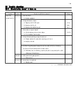
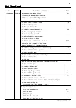
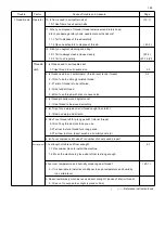
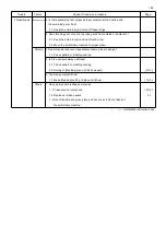
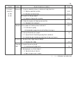
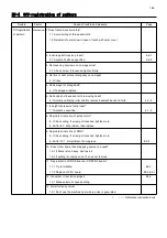
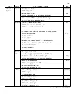
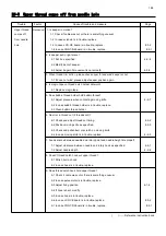
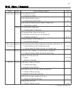
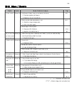
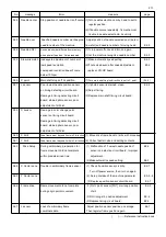
E9-5 Upper thread comes off from needle hole
Trouble Factor Cause of trouble and measure
Page
Upper thread
Mechanical
1. Is keeper in motion?
comes off 1-1 Check if cable was cut or there is something unusual.
from needle 1-2 In case solenoid is in trouble, replace.
hole 1-3 In case LCD-CE board is in trouble, replace. E3-2
1-4 In case CONT-R2 board is in trouble, replace. E2-1
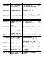
2. Is keeper put in right place?
2-1 Put it as specified. 4-5-8
2-2 Modify bent of keeper.
2-3 Adjust it again if movement is not smooth. 4-5-8
3. When thread trim action, please check upper thread wind keeper or not.
3-1 If dose not wind, please adjust keeper position again.
4. Is magic-tape on thread catch holder not worn?
4-1 Replace magic-tape.
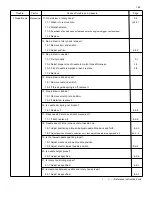
5. Does bobbin thread holder hold bobbin thread?
5-1 Adjust pressure when contacting moving knife. 4-5-7
5-2 In case bobbin thread holder is in trouble, replace.
5-3 Clean bobbin thread holder.
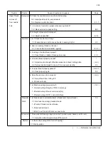
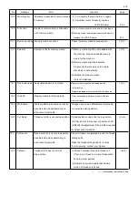
6. No error in thread cut (2 threads cut)?
6-1 Check and adjust thread cut timing. 4-5-2
6-2 Position moving knife as specified. 4-5-5
6-3 Check and polish burr or scratch on moving knife.
6-4 In case moving knife is in trouble, replace. 4-5-3
7. Are clearance between needle and rotary point and needle height are proper?
7-1 Adjust clearance between needle and rotary hook as specified. 4-4-1
7-2 Adjust needle depth. 4-2-6
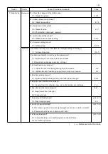
8. Doesn't thread catch hook cut upper thread?
8-1 Polish burr on hook.
8-2 In case hook is in trouble, replace.
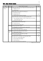
9. Does thread catch hook hold upper thread?
9-1 Check if cable was cut or there is something unusual.
9-2 In case pulse motor is in trouble, replace.
9-3 Adjust fixing position. 4-1-6
9-4 If hook is bent, modify.
9-5 In case hook is in trouble, replace.
9-6 In case LCD-CE board is in trouble, replace. E3-2
9-7 In case CONT-R2 board is in trouble, replace. E2-1
( ) ----- Reference instruction book
Summary of Contents for HCR3-1502
Page 1: ... Maintenance Manual for Embroidery Machine HCR3E SERIES Version 1 2 HappyJapan Inc ...
Page 104: ...105 4 7 3 Adjustment of timing detecting unit 8 Finally put the cover back on ...
Page 107: ...107 ...
Page 172: ...172 E7 Electric system diagram E7 1 Pulse motor driver PMD wiring ...
Page 173: ...173 E7 2 Pulse motor driver PMD setup ...
Page 174: ...174 E7 3 Inverter wiring ...
Page 175: ...175 E7 4 Electrical connection diagram ...
Page 176: ...176 ...
Page 177: ...177 ...
Page 178: ...178 E7 5 List of electrical connection diagram ...
Page 179: ...179 ...
Page 180: ...180 E7 6 Explanation of function clrcuit board HCD8122 LCD CE MX Board Ass y ...
Page 181: ...181 HCD8116 TP SW Circuit Board Ass y CN No Function CN1 Switch output LED input ...

