123
E2-9
Exchange Pulse Motor Driver
<
note
>
Make sure power plug is disconnected during
the
process
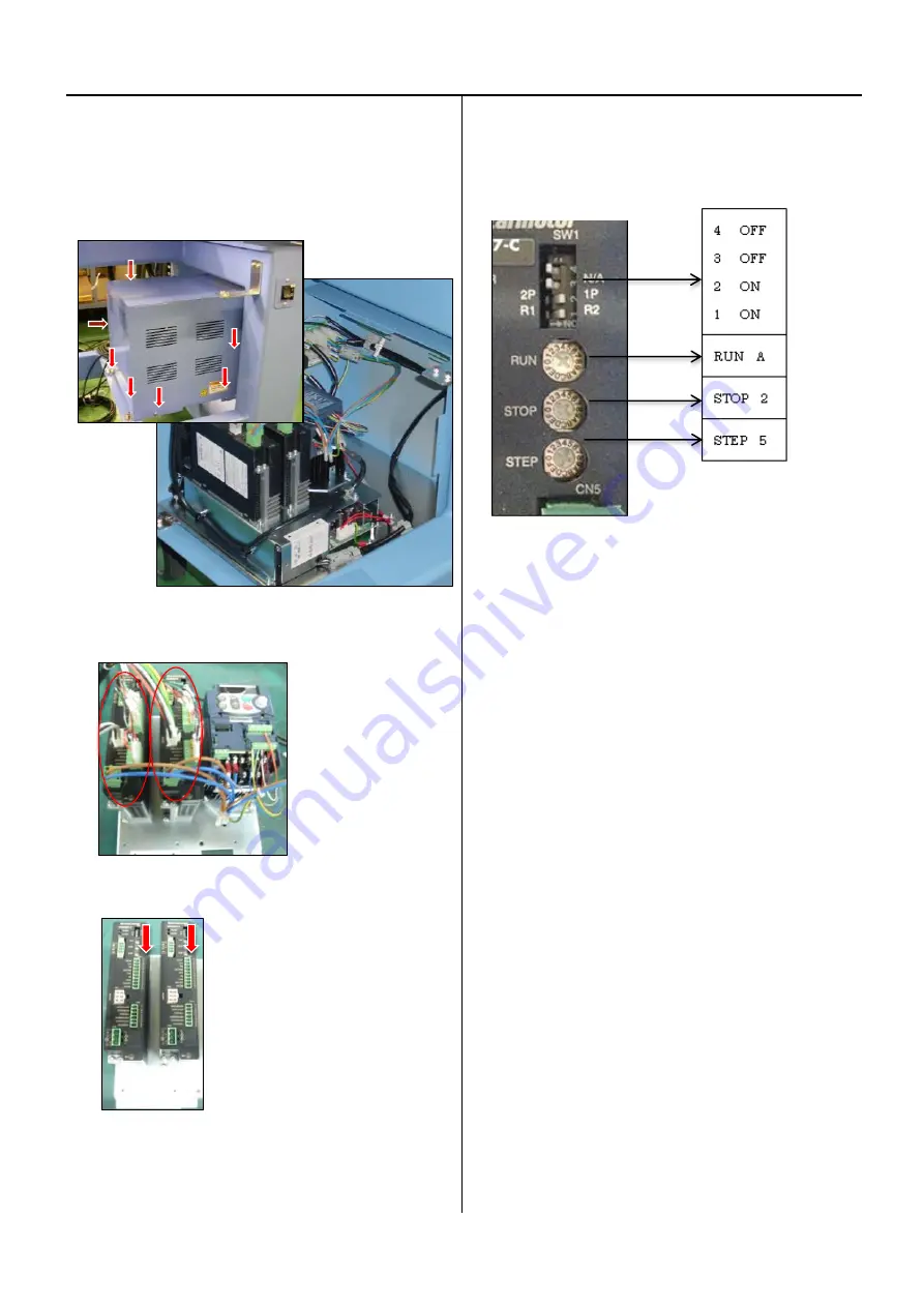
1. Remove power supply box.
Remove the screws at the seven places below.
2. Take harnesses out from driver.
3. Unscrew 4 screws on base plate.
4. Check setting of new driver (same setting for X and Y)
5. Fix driver by screws and connect harnesses, and put cover.
Detail information about harnesses connection is
mentioned in [E7-1 Pulse motor driver (PMD) wiring]
Summary of Contents for HCR3-1502
Page 1: ... Maintenance Manual for Embroidery Machine HCR3E SERIES Version 1 2 HappyJapan Inc ...
Page 104: ...105 4 7 3 Adjustment of timing detecting unit 8 Finally put the cover back on ...
Page 107: ...107 ...
Page 172: ...172 E7 Electric system diagram E7 1 Pulse motor driver PMD wiring ...
Page 173: ...173 E7 2 Pulse motor driver PMD setup ...
Page 174: ...174 E7 3 Inverter wiring ...
Page 175: ...175 E7 4 Electrical connection diagram ...
Page 176: ...176 ...
Page 177: ...177 ...
Page 178: ...178 E7 5 List of electrical connection diagram ...
Page 179: ...179 ...
Page 180: ...180 E7 6 Explanation of function clrcuit board HCD8122 LCD CE MX Board Ass y ...
Page 181: ...181 HCD8116 TP SW Circuit Board Ass y CN No Function CN1 Switch output LED input ...

