10
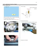
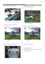
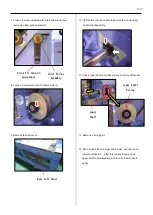
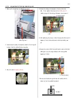
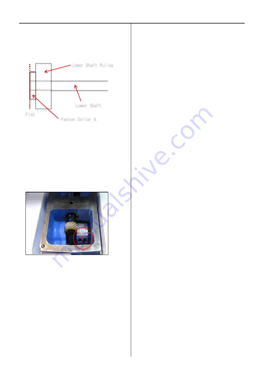
14. Put a lower shaft and a fasten collar A together to make
their surfaces flat, and then tighten a screw on the fatsen
collar A.
15. Put an idler pulley assembly back on.
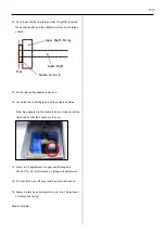
16. Let a disk reach 25 degrees, and then tighten screws.
Note: As appeared in the picture below, screws should be
tightened so that they will come face up.
17. Go to “4-7-2 Adjustment of upper shaft timing belt
Tension” for more information on timing belt adjustment.
18. Put rear left cover, left cover and bed cover B back on.
19. Adjust a rotary hook timing referring to “4-4-1 Adjustment
of rotary hook timing”.
Steps complete.
Flat
Fasten Collar A
Lower Shaft
Lower Shaft Pulley
Summary of Contents for HCR3-1502
Page 1: ... Maintenance Manual for Embroidery Machine HCR3E SERIES Version 1 2 HappyJapan Inc ...
Page 104: ...105 4 7 3 Adjustment of timing detecting unit 8 Finally put the cover back on ...
Page 107: ...107 ...
Page 172: ...172 E7 Electric system diagram E7 1 Pulse motor driver PMD wiring ...
Page 173: ...173 E7 2 Pulse motor driver PMD setup ...
Page 174: ...174 E7 3 Inverter wiring ...
Page 175: ...175 E7 4 Electrical connection diagram ...
Page 176: ...176 ...
Page 177: ...177 ...
Page 178: ...178 E7 5 List of electrical connection diagram ...
Page 179: ...179 ...
Page 180: ...180 E7 6 Explanation of function clrcuit board HCD8122 LCD CE MX Board Ass y ...
Page 181: ...181 HCD8116 TP SW Circuit Board Ass y CN No Function CN1 Switch output LED input ...


