40
4-2-1 Assemble and remove moving head (except for 1
st
head)
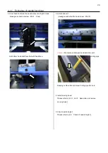
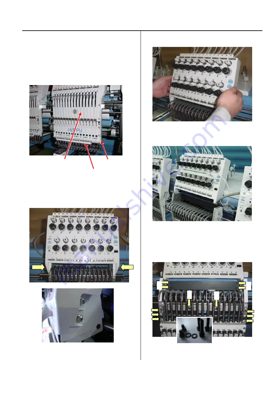
1. Remove moving head.
1-1. Set moving head at position that 15
th
needle is active.
Remove the front panel (upper), cord clip and lighting
bracket.
(Truss head screw : M4-6 4 pcs)
Upper shaft cover
Cord clip
Lighting bracket
1-2. Loosen screw on thread tension bracket
(Pan head screw : M4-10 4 pcs)
1-3. Remove the thread tension bracket.
(Pull thread tension bracket to front)
Put thread tension bracket and lighting bracket on head
upper cover.
1-4. Remove the set screw.
A (Hexagon socket head cap screw : M4-20 6 pcs)
B (Hexagon socket head cap screw : M4-6 2 pcs)
C (Hexagon socket head cap screw : M4-18 4 pcs)
Hexagon socket head cap screw is a set with plain washer.
Please keep as a set.
B
B
C
C
A
A
Summary of Contents for HCR3-1502
Page 1: ... Maintenance Manual for Embroidery Machine HCR3E SERIES Version 1 2 HappyJapan Inc ...
Page 104: ...105 4 7 3 Adjustment of timing detecting unit 8 Finally put the cover back on ...
Page 107: ...107 ...
Page 172: ...172 E7 Electric system diagram E7 1 Pulse motor driver PMD wiring ...
Page 173: ...173 E7 2 Pulse motor driver PMD setup ...
Page 174: ...174 E7 3 Inverter wiring ...
Page 175: ...175 E7 4 Electrical connection diagram ...
Page 176: ...176 ...
Page 177: ...177 ...
Page 178: ...178 E7 5 List of electrical connection diagram ...
Page 179: ...179 ...
Page 180: ...180 E7 6 Explanation of function clrcuit board HCD8122 LCD CE MX Board Ass y ...
Page 181: ...181 HCD8116 TP SW Circuit Board Ass y CN No Function CN1 Switch output LED input ...

