6
7
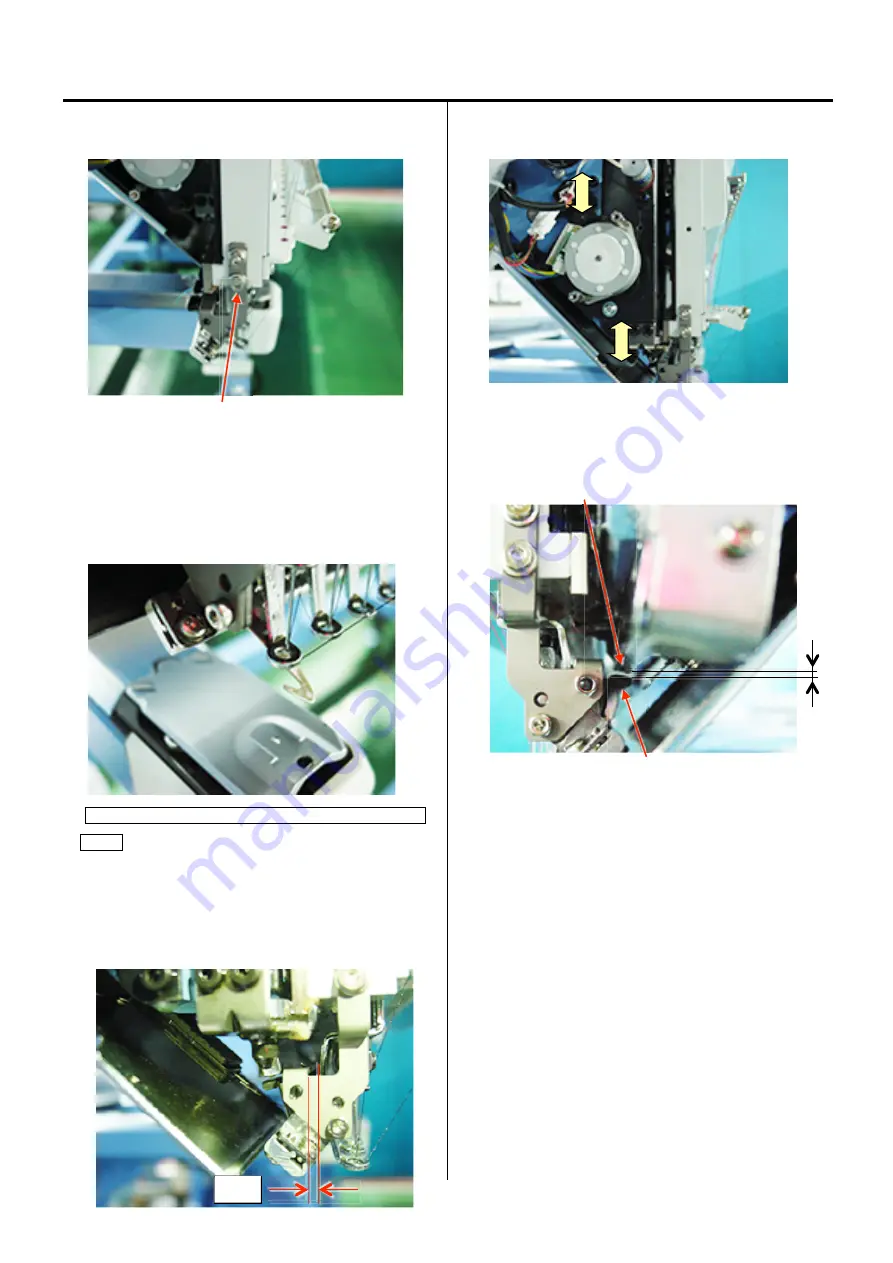
4-2-16 Adjustment of clip-type thread holder
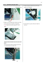
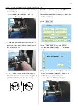
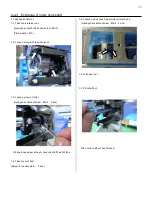
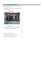
1. Loosen screw to the extent that clip-type thread hoIder
moves. (Fixing screw 4 pcs)
Screw
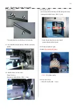
2. Please put out and withdraw thread catcher by your finger
and fix holder position at smoothly moving position.
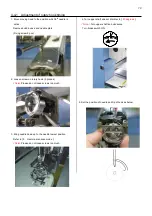
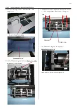
Hook has to touch surface of clip holder (lower).
< Note >
Please check smooth moving at 1
st
and 15
th
needle.
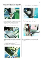
Positional relationship between pressure foot and holder
(lower)
When downing the needle, should have gap more than
1 mm between holder and presser foot.
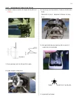
When is hook pull out, space between hook and bottom of
pressure foot should be more than 1mm.
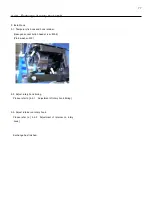
3. Thread catcher device should be adjusted if above
clearance is not keepable.
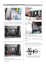
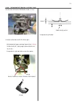
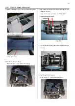
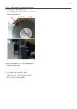
4. Space between Clip drive and clip should be 1-2mm.
< Note >
Please check at 1
st
and 15
th
needle.
Clip drive
Clip
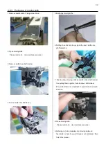
5. Press thread trim key and confirm whole thread trim
revolution.
Gap
Summary of Contents for HCR3-1502
Page 1: ... Maintenance Manual for Embroidery Machine HCR3E SERIES Version 1 2 HappyJapan Inc ...
Page 104: ...105 4 7 3 Adjustment of timing detecting unit 8 Finally put the cover back on ...
Page 107: ...107 ...
Page 172: ...172 E7 Electric system diagram E7 1 Pulse motor driver PMD wiring ...
Page 173: ...173 E7 2 Pulse motor driver PMD setup ...
Page 174: ...174 E7 3 Inverter wiring ...
Page 175: ...175 E7 4 Electrical connection diagram ...
Page 176: ...176 ...
Page 177: ...177 ...
Page 178: ...178 E7 5 List of electrical connection diagram ...
Page 179: ...179 ...
Page 180: ...180 E7 6 Explanation of function clrcuit board HCD8122 LCD CE MX Board Ass y ...
Page 181: ...181 HCD8116 TP SW Circuit Board Ass y CN No Function CN1 Switch output LED input ...


