119
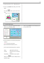
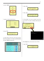
11. Press Machine Test
11. Press #1 Needle Adjust and press Position
13. Turn shaft of potentiometer
and set position where * mark
and needle number (15)
appear on screeen with
sound.
14. Set potentiometer and fix
<check>
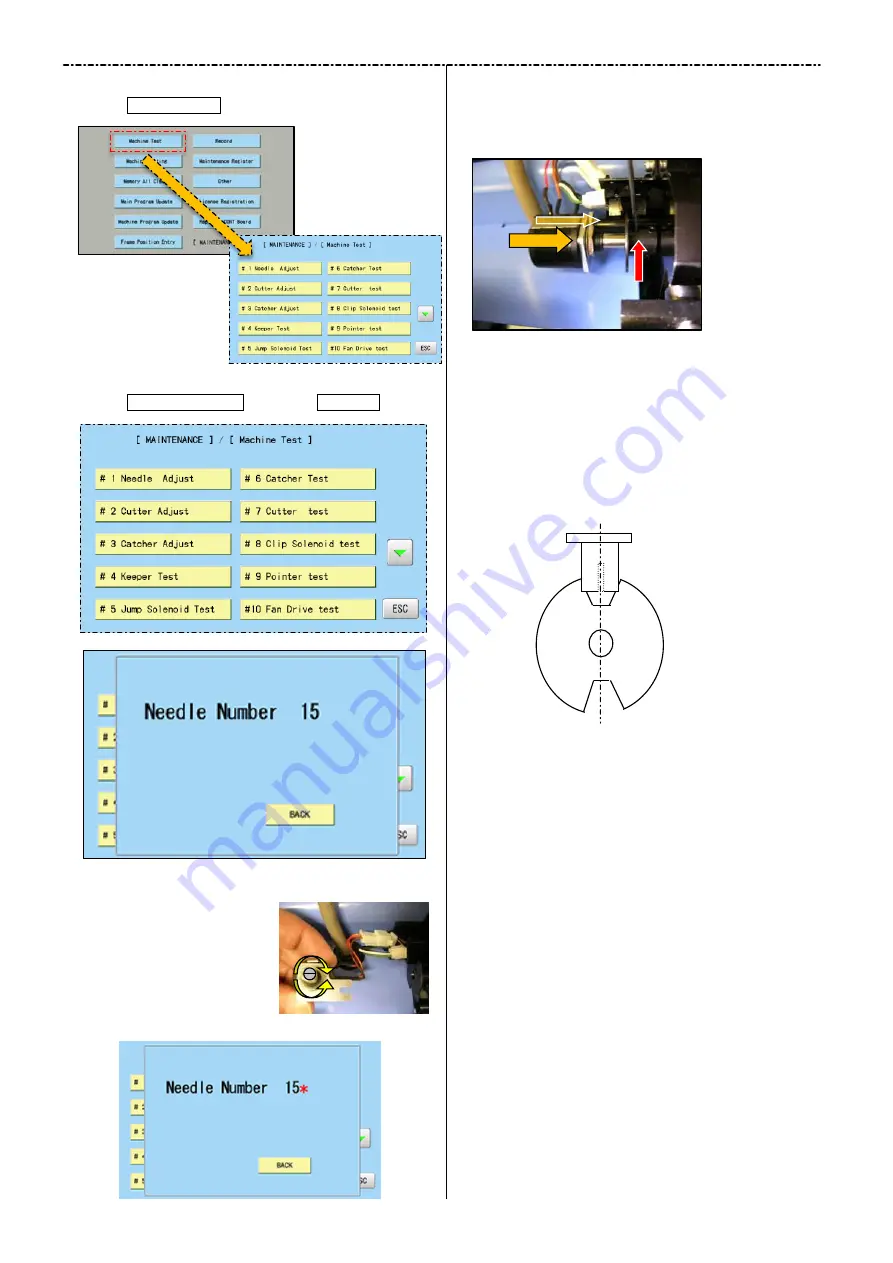
Sensor is located at notch center of slit collar and * mark
is shown on creen
The position of sensor is not lacated at notch of slit collar,
re-adjust again
15. Turn knob and move head to 1
st
needle position
<check>
* mark appears, when notch center of slit collar comes
sensor position. If position is not matching, please re-adjust
again
Sensor
Slit
Center
Summary of Contents for HCR3-1502
Page 1: ... Maintenance Manual for Embroidery Machine HCR3E SERIES Version 1 2 HappyJapan Inc ...
Page 104: ...105 4 7 3 Adjustment of timing detecting unit 8 Finally put the cover back on ...
Page 107: ...107 ...
Page 172: ...172 E7 Electric system diagram E7 1 Pulse motor driver PMD wiring ...
Page 173: ...173 E7 2 Pulse motor driver PMD setup ...
Page 174: ...174 E7 3 Inverter wiring ...
Page 175: ...175 E7 4 Electrical connection diagram ...
Page 176: ...176 ...
Page 177: ...177 ...
Page 178: ...178 E7 5 List of electrical connection diagram ...
Page 179: ...179 ...
Page 180: ...180 E7 6 Explanation of function clrcuit board HCD8122 LCD CE MX Board Ass y ...
Page 181: ...181 HCD8116 TP SW Circuit Board Ass y CN No Function CN1 Switch output LED input ...


