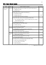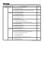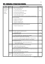
190
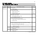
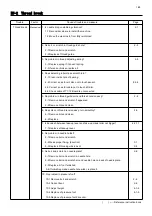
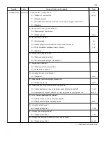
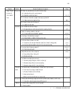
Trouble Factor Cause of trouble and measure Page
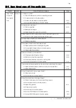
Thread break
Mechanical
11. No problem in rotary hook? 2-8
11-1 Clean it to remove lints.
( 23-2 )
11-2 Furbish scratch.
11-3
If backlash of bobbin case holder and outer hook grows bigger, replace them.
11-4 Replace.
12. No problem in rotary hook retainer?
12-1 Remove burr and scratch.
12-2 Adjust position.
4-4-2
13. No problem in needle?
13-1 Fix it properly . 3-1
13-2 Select proper size of needle to match thread thickness. 3-3
13-3 If tip of needle is warped or bent, replace. 2-8
13-4 Replace.
14. No problem in bobbin case?
14-1 Remove rust and scratch.
14-2 If thread guide spring is off, replace it.
15. No problem in bobbin?
15-1 Remove scratch (iron bobbin).
15-2 If distorted. replace it.
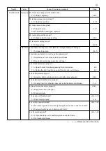
16. Is needle bar spring not broken?
16-1 Replace it. 4-2-9
17. Does needle bar make smooth movement?
17-1 If bent, replace it. 4-2-9
18. Needle doesn't drop in the center of needle hole.
18-1 Adjust positioning plate and adjust needle drop back and forth. 4-2-3
18-2
Adjust position of needle selection unit, then adjust needle drop right and left. 4-2-4, -5
19. Is the lowest needle position proper?
19-1 Adjust mechanical lowest needle position.
19-2 Adjust electric lowest needle position.
E2-2
20. Is needle height proper?
20-1 Adjust as specified. 4-2-6
21. Is rotary hook timing proper?
21-1 Adjust as specified. 4-4-1
22. Is clearance between needle and rotary hook proper?
22-1 Adjust as specified. 4-4-1
( ) ----- Reference instruction book
Summary of Contents for HCR3-1502
Page 1: ... Maintenance Manual for Embroidery Machine HCR3E SERIES Version 1 2 HappyJapan Inc ...
Page 104: ...105 4 7 3 Adjustment of timing detecting unit 8 Finally put the cover back on ...
Page 107: ...107 ...
Page 172: ...172 E7 Electric system diagram E7 1 Pulse motor driver PMD wiring ...
Page 173: ...173 E7 2 Pulse motor driver PMD setup ...
Page 174: ...174 E7 3 Inverter wiring ...
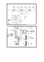
Page 175: ...175 E7 4 Electrical connection diagram ...
Page 176: ...176 ...
Page 177: ...177 ...
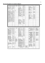
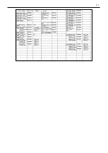
Page 178: ...178 E7 5 List of electrical connection diagram ...
Page 179: ...179 ...
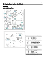
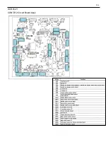
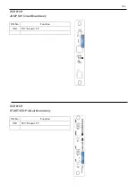
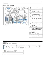
Page 180: ...180 E7 6 Explanation of function clrcuit board HCD8122 LCD CE MX Board Ass y ...
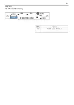
Page 181: ...181 HCD8116 TP SW Circuit Board Ass y CN No Function CN1 Switch output LED input ...


