10
5
5 User maintenance mode
User maintenance mode has the items as below.
Change jump
Change the needle bar’s movement.
“JUMP” : Needle Jump, “DRIVE” : Needle Drive
Upper shaft turns Upper shaft turns clockwise and counterclockwise.
When release button, upper shaft stops.
Needle change
Move the sewing head to the adjustment needle in the direction of the arrows.
[Cut] Cutter Open/Close
Open and close knife of thread trimming
[Catch] Cathcer Open/Close
Open and close thread catcher
[Clip] Clip-type thread holder (option)
Open and close clip-type thread holder
[Keeper] Keeper Open/Close
Open and close keeperr
[Origin] Standby position
In case, each equipment position without standby position, as example “Upper shaft is not
at C point, Thread cut blade is not at stop position, Thread Catcher is open position”, this
key work for back to standby position automatically.
Indicates point which sensors are active.
L point sensor
The point that indicator becomes RED is L-point, when main shaft is turned.
C point sensor
The point that indicator becomes RED is C-point, when main shaft is turned.
Needle sensor
The point that indicator becomes RED is needle position, when moving head is moved
Origin point of cutter
The point that indicator becomes RED is origin point of cutter
Origin point of thread catcher The point that indicator becomes RED is origin point of thread cacther
Angle
Indicate angle of main shaft.
Please use “Dial” on upper shaft, when you need to know precise angle.
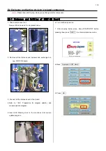
5-1 How to enter “User Maintenance Mode”
1. When the machine is stopped, press
and
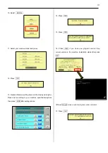
2. Press ”OTHER”.
3. Press ”Maintenance”.
The display shows as below.
Summary of Contents for HCR3-1502
Page 1: ... Maintenance Manual for Embroidery Machine HCR3E SERIES Version 1 2 HappyJapan Inc ...
Page 104: ...105 4 7 3 Adjustment of timing detecting unit 8 Finally put the cover back on ...
Page 107: ...107 ...
Page 172: ...172 E7 Electric system diagram E7 1 Pulse motor driver PMD wiring ...
Page 173: ...173 E7 2 Pulse motor driver PMD setup ...
Page 174: ...174 E7 3 Inverter wiring ...
Page 175: ...175 E7 4 Electrical connection diagram ...
Page 176: ...176 ...
Page 177: ...177 ...
Page 178: ...178 E7 5 List of electrical connection diagram ...
Page 179: ...179 ...
Page 180: ...180 E7 6 Explanation of function clrcuit board HCD8122 LCD CE MX Board Ass y ...
Page 181: ...181 HCD8116 TP SW Circuit Board Ass y CN No Function CN1 Switch output LED input ...

