196
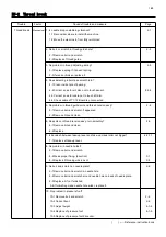
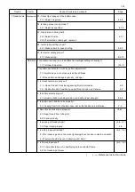
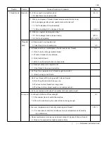
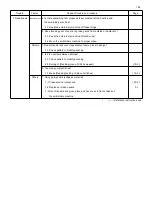
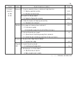
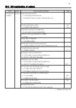
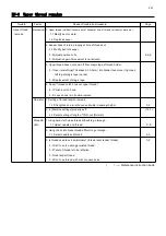
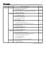
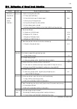
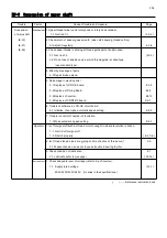
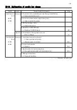
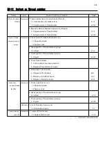
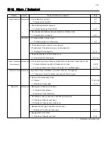
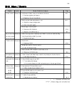
E9-4 Off-registration of pattern
Trouble Factor Cause of trouble and measure Page
Off-registration
Mechanical
1. Does frame move smoothly?
of pattern
1-1 Avoid curling of thread and cloth.
1-2 Reinstall of outer cover in case of touch with outer cover.
2. Is carriage belt tension proper? 4-6-1
2-1 Adjust all belts as specified. 4-6-3
3. No loosening of screws on carriage drive?
3-1 Check screw. If loosened, tighten firmly.
4. No lints or dust around idler pulley on carriage?
4-1 Clean
5. No damage in carriage belt?
5-1 If damaged, replace.
6. No backlash of back and forth in moving head?
6-1 Adjust positioning roller shaft to remove backlash back and forth. 4-2-3
7. Is height of pressure foot proper?
7-1 Adjust as specified. 4-1-4
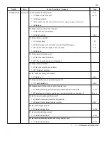
8. No problem in motion of pulse motor?
8-1 Check wiring. If screw got loosened, tighten more.
8-2 After 9-1, still problem, then replace.
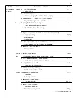
9. No problem in motion of PMD ?
9-1 Check wiring. If screw got loosened, tighten more.
9-2 After 10-1, still problem, then replace. E2-9
10. Does't other frame than Happy's genuine one used?
10-1 If frame is too heavy, don't use it.
10-2 If setting is not proper, set it so as not to move.
11. No problem in LCD-CE board or CONT-R2 boaer ?
11-1 Try to initialize. E4-3
11-2 Replace of CPU board. E3-2,E2-1
12. Is number of revolution proper? E4-3
12-1 Make automatic speed setting.
13. Not affected by noise?
13-1 Don't use the machine near where noise is generated.
( ) ----- Reference instruction book
Summary of Contents for HCR3-1502
Page 1: ... Maintenance Manual for Embroidery Machine HCR3E SERIES Version 1 2 HappyJapan Inc ...
Page 104: ...105 4 7 3 Adjustment of timing detecting unit 8 Finally put the cover back on ...
Page 107: ...107 ...
Page 172: ...172 E7 Electric system diagram E7 1 Pulse motor driver PMD wiring ...
Page 173: ...173 E7 2 Pulse motor driver PMD setup ...
Page 174: ...174 E7 3 Inverter wiring ...
Page 175: ...175 E7 4 Electrical connection diagram ...
Page 176: ...176 ...
Page 177: ...177 ...
Page 178: ...178 E7 5 List of electrical connection diagram ...
Page 179: ...179 ...
Page 180: ...180 E7 6 Explanation of function clrcuit board HCD8122 LCD CE MX Board Ass y ...
Page 181: ...181 HCD8116 TP SW Circuit Board Ass y CN No Function CN1 Switch output LED input ...

