112
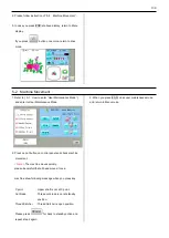
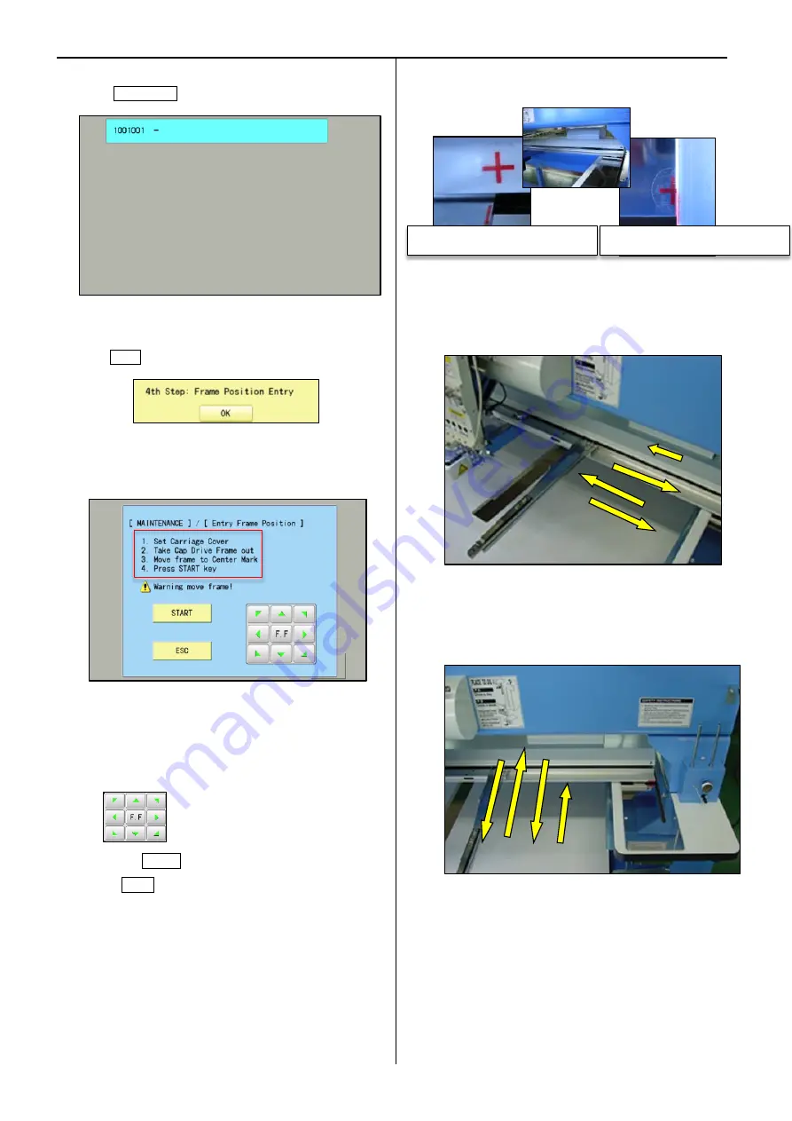
18. Press 1001001-
19.Press OK
20. Operate following below instructions
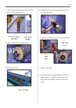
(1). Fix carriage cover
(2). Remove cap frame
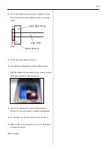
(3). Move carriage to center mark position by
. (Refer to below display)
(4). Press START button
(Press ESC button in case of cancellation)
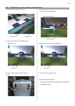
21. When you press START button, registation of X axis
direction will start. Frame moves as below.
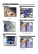
22. Then registration of Y axis direction will starat.
Frame moves as below.
Center mark position of X axis
Center mark position of Y axis
1
2
3
4
1
2
3
4
Summary of Contents for HCR3-1502
Page 1: ... Maintenance Manual for Embroidery Machine HCR3E SERIES Version 1 2 HappyJapan Inc ...
Page 104: ...105 4 7 3 Adjustment of timing detecting unit 8 Finally put the cover back on ...
Page 107: ...107 ...
Page 172: ...172 E7 Electric system diagram E7 1 Pulse motor driver PMD wiring ...
Page 173: ...173 E7 2 Pulse motor driver PMD setup ...
Page 174: ...174 E7 3 Inverter wiring ...
Page 175: ...175 E7 4 Electrical connection diagram ...
Page 176: ...176 ...
Page 177: ...177 ...
Page 178: ...178 E7 5 List of electrical connection diagram ...
Page 179: ...179 ...
Page 180: ...180 E7 6 Explanation of function clrcuit board HCD8122 LCD CE MX Board Ass y ...
Page 181: ...181 HCD8116 TP SW Circuit Board Ass y CN No Function CN1 Switch output LED input ...

