207
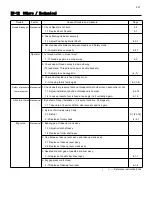
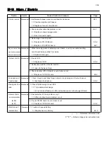
E9-12 Others / Mechanical
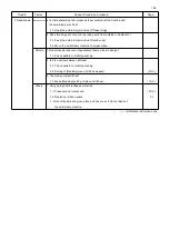
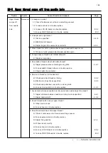
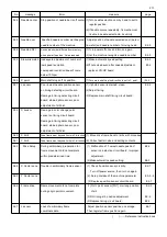
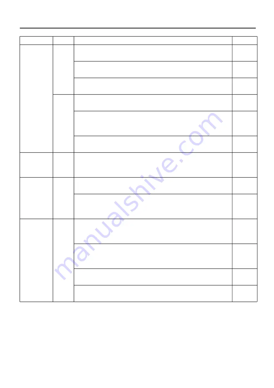
Trouble Factor Cause of trouble and measure
Page
Needle Breakage
Mechanical
1. Check Needle is not bent. 2-8
1-1 Replace bent Needle. 3-1
2. Check Moving Head set securely.
2-1 Adjust Positioning Roller Shaft. 4-2-3
3. Secure adequate distance between Needle and Rotary Hook.
3-1 Adjust distance properly. 4-4-1
Operator 1. Is thread method in proper way?
1-1 Threading again in a proper way. 2-9
2. Check upper thread comes in a smooth way.
(Thread stand, Thread tension point, double back etc)
2-1 Adjust place be caught in. ( 4-7 )
3. Check whether fabric is fixed firmly or not.
3-1 Hooping fabric firmly again. ( 6-3, 7-6)
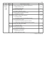
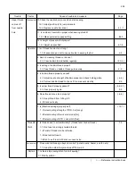
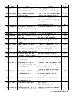
Defect of pressure
Mechanical
1. Check whether pressure foot and thread catcher holder touch each other or not.
foot movement
1-1 Adjust installment position of thread catch holder. 4-2-14
1-2 In case pressure foot is fixed at an angle, fix it vertically again. 4-1-4
Abnormal noise
Mechanical
1. By defect of cover installation. (Pressure foot drive, Carriage etc)
1-1 Take care of insert condition, clearance etc and fix again.
2. By lack of oil inside rotary hook.
2-1 Refuel 2-7,(23-1b)
2-2 Replace of rotary hook 4-4-1
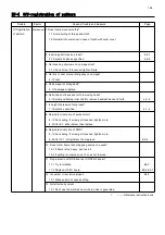
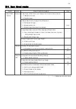
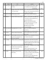
Big noise
Mechanical
1. Bearing gap of take up crank ass’y.
1-1 Adjust roller shaft ass’y.
1-2 Replace of roller shaft ass’y.
2. Gap between take up lever ass’y and take up clank ass’y.
2-1 Replace of take up lever ass’y.
2-2 Replace of take up lever crank ass’y
3. Needle bar driver gap of needle bar driver ass’y.
3-1 Replace of needle bar driver ass’y. 4-1-1
4. Big gap pressure foot cam
4-1 Replace of take-up lever cam. 4-1-8
( ) ----- Reference instruction book
Summary of Contents for HCR3-1502
Page 1: ... Maintenance Manual for Embroidery Machine HCR3E SERIES Version 1 2 HappyJapan Inc ...
Page 104: ...105 4 7 3 Adjustment of timing detecting unit 8 Finally put the cover back on ...
Page 107: ...107 ...
Page 172: ...172 E7 Electric system diagram E7 1 Pulse motor driver PMD wiring ...
Page 173: ...173 E7 2 Pulse motor driver PMD setup ...
Page 174: ...174 E7 3 Inverter wiring ...
Page 175: ...175 E7 4 Electrical connection diagram ...
Page 176: ...176 ...
Page 177: ...177 ...
Page 178: ...178 E7 5 List of electrical connection diagram ...
Page 179: ...179 ...
Page 180: ...180 E7 6 Explanation of function clrcuit board HCD8122 LCD CE MX Board Ass y ...
Page 181: ...181 HCD8116 TP SW Circuit Board Ass y CN No Function CN1 Switch output LED input ...

