13
Lock nut
Tighten
the lock nut
Lower
Higher
Bolt
Pipe cover
Water level
Head bed
Block base
Rubber mount
2-1, 2-2 Setting up the machine
2-1 Machine installation
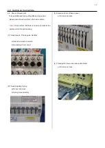
(1) place block base and rubber mount under bolts and adjust
bolts so that the machine becomes level.
Block bases and rubber mounts are included in
accessories.
At this moment, get caster slightly risen from the floor.
As shown in Fig., levelers should be placed on both sides
of head bed with upper cover removed.
(2) Fix the lock nut.
(3) Fix the pipe cover.
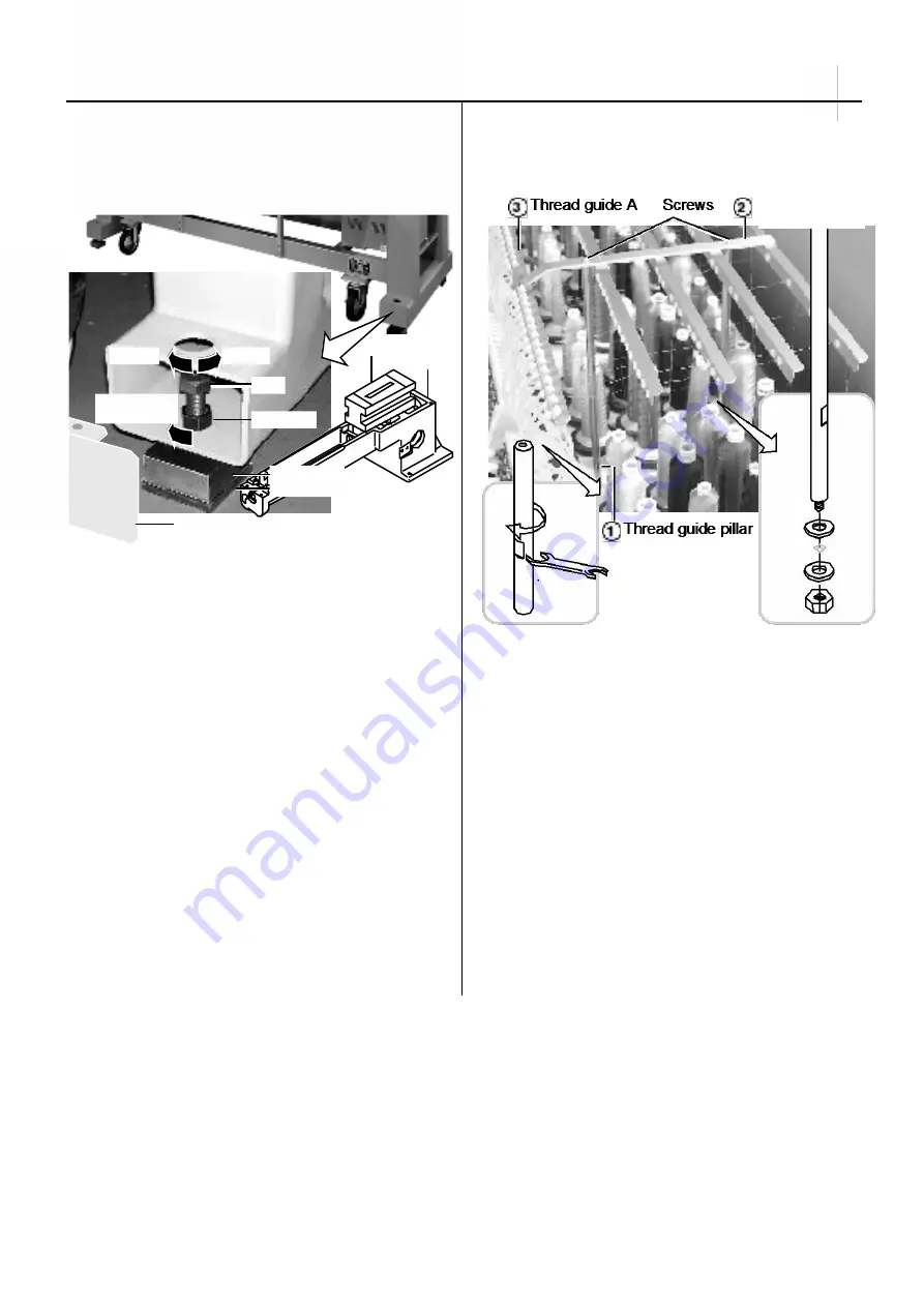
2-2 Assemble the thread guide
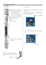
(1) Turn the thread guide pillar (front [long], rear [short])
clockwise with a spanner until tight.
Fix rear thread guide pillar with a washer and a nut (M8).
<Spanner> 10mm, 13mm
(2) Install the thread guide ass'y with supplied screws (M4x8).
(3) Fix thread guide A (with spiral tube) on thread guide ass'y
with screws (M3x8) from lower side.
Summary of Contents for HCR3-1502
Page 1: ... Maintenance Manual for Embroidery Machine HCR3E SERIES Version 1 2 HappyJapan Inc ...
Page 104: ...105 4 7 3 Adjustment of timing detecting unit 8 Finally put the cover back on ...
Page 107: ...107 ...
Page 172: ...172 E7 Electric system diagram E7 1 Pulse motor driver PMD wiring ...
Page 173: ...173 E7 2 Pulse motor driver PMD setup ...
Page 174: ...174 E7 3 Inverter wiring ...
Page 175: ...175 E7 4 Electrical connection diagram ...
Page 176: ...176 ...
Page 177: ...177 ...
Page 178: ...178 E7 5 List of electrical connection diagram ...
Page 179: ...179 ...
Page 180: ...180 E7 6 Explanation of function clrcuit board HCD8122 LCD CE MX Board Ass y ...
Page 181: ...181 HCD8116 TP SW Circuit Board Ass y CN No Function CN1 Switch output LED input ...


