49
4-2-3 Adjustment of needle position (back and front)
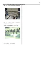
1. Please set Thread break detecting switch to ON for
adjusting head. Other head, please set to JUMP.
2. Push and pull the Moving head and check playing the
moving head.
In case of you find play the moving head
Loose screw of positioning roller and re-tight the screw with
jyointing the Rail.
Rail
Screw
3. Move the Moving head to 8
th
needle, then down needle till
needle point to face of needle plate.
Please refer to [ 5 User maintenance mode ].
4. Move the Positioning plate to front and back for adjust
needle position against needle hole to center and tight the
screw.
< Note >
Insert Lower rail to between the two bearing
deeply.
Positioning plate
Needle Needle hole of needle plate
5. After adjustment, confirm the position by 1
st
and 15
th
needle also.
If you have big different the needle position 8
th
and 1
st
and
15
th
needle, please confirm again after you replate bland
new needle.
6. After adjustment, please be sure to check and adjust
clearance between needle and shuttle hook.
Please refer to [ 4-4-1 Adjustment of rotary hook timing ].
Summary of Contents for HCR3-1502
Page 1: ... Maintenance Manual for Embroidery Machine HCR3E SERIES Version 1 2 HappyJapan Inc ...
Page 104: ...105 4 7 3 Adjustment of timing detecting unit 8 Finally put the cover back on ...
Page 107: ...107 ...
Page 172: ...172 E7 Electric system diagram E7 1 Pulse motor driver PMD wiring ...
Page 173: ...173 E7 2 Pulse motor driver PMD setup ...
Page 174: ...174 E7 3 Inverter wiring ...
Page 175: ...175 E7 4 Electrical connection diagram ...
Page 176: ...176 ...
Page 177: ...177 ...
Page 178: ...178 E7 5 List of electrical connection diagram ...
Page 179: ...179 ...
Page 180: ...180 E7 6 Explanation of function clrcuit board HCD8122 LCD CE MX Board Ass y ...
Page 181: ...181 HCD8116 TP SW Circuit Board Ass y CN No Function CN1 Switch output LED input ...


