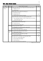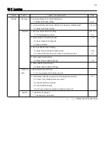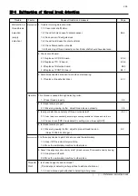
200
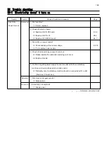
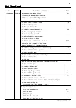
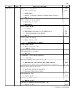
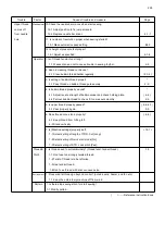
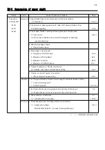
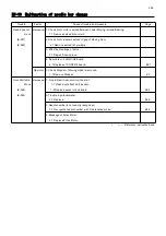
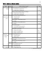
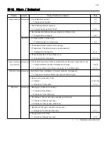
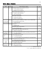
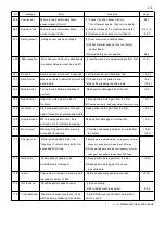
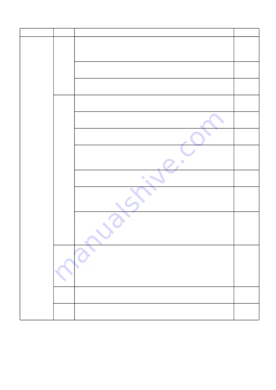
Trouble Factor Cause of trouble and measure
Page
Upper thread
Mechanical
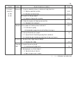
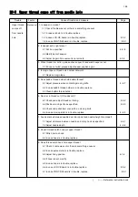
10.Check the needle bar moves when start sewing.
comes off 12-1 Adjust position to fix jump solenoid.
from needle 12-2 Replace needle bar driver. 4-1-1
hole 11. Is number of revolution proper when sewing started?
13-1 Make automatic speed setting. E4-3
12.Is height of pressure foot proper?
14-1 Adjust as specified. 4-1-4
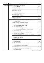
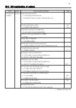
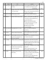
Operator 1. Isn't thread tension too strong?
1-1 Weaken tension not to cause trouble in sewing rhythm. 2-9
2. Keen in cleaning thread cut device?
2-1 Clean bobbin thread holder regularly. ( 23-2 )
3. Is setting of bobbin thread proper?
*
3-1 Pass thread on bobbin thread guide surely. 2-9
4. Is bobbin thread properly wound?
*
4-1 Adjust tensile strength of bobbin winder and check holding plate. ( 4-4 )
4-2 Pull out bobbin thread to check if it comes out smoothly. 2-9
5. Is upper thread properly passed?
( 4-6, 4-7 )
5-1 Pass properly again. 2-9
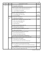
6. Does thread cone stand properly?
( 4-6 )
6-1 Keep thread from hitting felt.
6-2 Stand vertically.
7. Is [Machine settings] properly set? ( 15-1 )
7-1 Select setting of length of TRD. Cut [Long].
7-2 Select setting of Quick start mode [No].
7-3 Select setting of STR. Lock stitch [Yes].
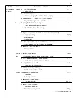
Thread & 1. Is thread used to suit embroidery? (thread twist, tender thread). 3-3
Cloth 1-1 Don't use too strongly twisted thread.
1-2 Twist of thread is to be left-wise.
1-3 Use tender thread.
1-4 Don't use thread with knot or uneven size.
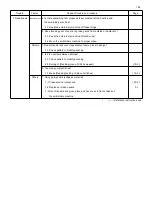
Environment
1. Does wind let thread go beyond control? (outside wind, heater, and fan etc.)
1-1 Keep the embroidery machine off from wind.
Pattern 1. Is there stop sewing stitch for start sewing?
1-1 Modify pattern.
( ) ----- Reference instruction book
Summary of Contents for HCR3-1502
Page 1: ... Maintenance Manual for Embroidery Machine HCR3E SERIES Version 1 2 HappyJapan Inc ...
Page 104: ...105 4 7 3 Adjustment of timing detecting unit 8 Finally put the cover back on ...
Page 107: ...107 ...
Page 172: ...172 E7 Electric system diagram E7 1 Pulse motor driver PMD wiring ...
Page 173: ...173 E7 2 Pulse motor driver PMD setup ...
Page 174: ...174 E7 3 Inverter wiring ...
Page 175: ...175 E7 4 Electrical connection diagram ...
Page 176: ...176 ...
Page 177: ...177 ...
Page 178: ...178 E7 5 List of electrical connection diagram ...
Page 179: ...179 ...
Page 180: ...180 E7 6 Explanation of function clrcuit board HCD8122 LCD CE MX Board Ass y ...
Page 181: ...181 HCD8116 TP SW Circuit Board Ass y CN No Function CN1 Switch output LED input ...

