16
5
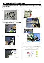
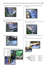
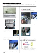
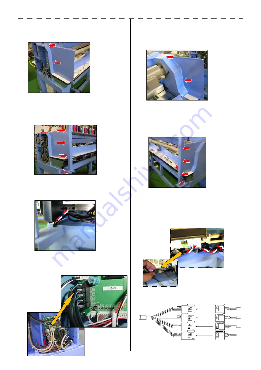
4. Remove screw of rmission (right), Install Safety Guard on
missin (right)
5. Remove screw of body, Fix Sencor (C) on body and fix to
Sefety Guard(B) by screws(F)
6.Pass harness into mission box
7. Connect harnessinto CN14 on Drive circuit board
RS4 -> CN14-RS4
RS3 -> CN14-RS3
RS2 -> CN14-RS2
RS1 -> CN14-RS1
RS5 -> CN13-RS5
8. Remove screw of rmission (left), Set Safety Guard (D) on
mission (left)
9. Remove screw of body, Fix Sencor (E) on body and fix to
Sefety Guard(D) by screws(F)
10. Connect harness to extension harness(LS*) at side of Y
carriage
<note>
put cable in order for avoiding to touch to shaft
LS1 <- LS1
LS2 <- LS2
LS3 <- LS3
LS4 <- LS4
Summary of Contents for HCR3-1502
Page 1: ... Maintenance Manual for Embroidery Machine HCR3E SERIES Version 1 2 HappyJapan Inc ...
Page 104: ...105 4 7 3 Adjustment of timing detecting unit 8 Finally put the cover back on ...
Page 107: ...107 ...
Page 172: ...172 E7 Electric system diagram E7 1 Pulse motor driver PMD wiring ...
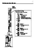
Page 173: ...173 E7 2 Pulse motor driver PMD setup ...
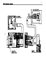
Page 174: ...174 E7 3 Inverter wiring ...
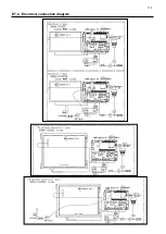
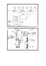
Page 175: ...175 E7 4 Electrical connection diagram ...
Page 176: ...176 ...
Page 177: ...177 ...
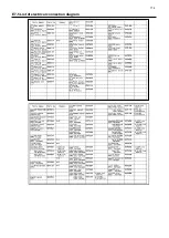
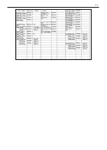
Page 178: ...178 E7 5 List of electrical connection diagram ...
Page 179: ...179 ...
Page 180: ...180 E7 6 Explanation of function clrcuit board HCD8122 LCD CE MX Board Ass y ...
Page 181: ...181 HCD8116 TP SW Circuit Board Ass y CN No Function CN1 Switch output LED input ...


