204
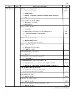
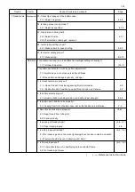
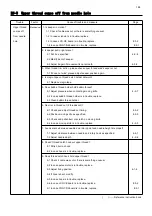
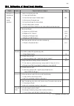
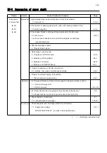
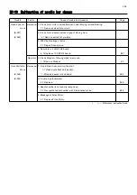
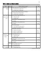
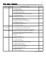
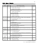
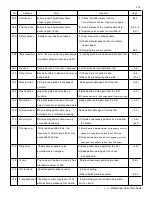
E9-9 Suspension of upper shaft
Trouble Factor Cause of trouble and measure
Page
Suspension
Mechanical
1. Upper thread twine round rotary hook or rotary hook retainer.
of main shaft 1-1 Get rid of it. ( 23-2 )
(E-18)
2. Check return of keeper goes smooth. (when start sewing, thread cutting.
(E-51) 2-1Adjust it regularly. 4-5-8
(E-52)
3. Check upper thread is sticking at thread guide part of bobbin case.
3-1 Get rid of it. ( 23-2 )
3-2 Do not use of bobbin case in which thread guide is coiled type.
(use standard type)
4. Effect by breakage of parts.
4-1 Repair broken place.
5. No damage in electric parts ?
5-1 Replace of LCD-CE board. E3-2
5-2 Replace of Timing Board. E2-2
5-3 Replace of inverter. E2-12
5-4 Replace of CONT-R2 board. E2-1
6. Trouble of software in LCD-CE circuit board.
6-1 Initialize, then make automatic speed setting. E4-3
7. Trouble in control of number of revolution.
7-1 Make automatic speed setting. E4-3
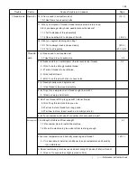
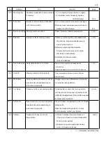
Operator 1. Isn't foreign stuff such as thread or cloth caught in where revolution is driven.
1-1 Get rid of foreign stuff.
1-2 Stretch properly. ( 6-3, 7-6 )
2. Isn't thread tension too strong (stop at time of action of thread cut)?
2-9
2-1 Weaken tension so as not to cause trouble in sewing rhythm.
3. Check condition of lubrication. 2-7
3-1 Lubricate (refer to message) ( 23-1b )
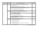
Environment
1. Check adequate level of voltage (refer to trip of inverter).
1-1 Supply rated voltage. ( 23-1 )
200V:220V:230V:240V (It varies in the specifications.)
( ) ----- Reference instruction book
Summary of Contents for HCR3-1502
Page 1: ... Maintenance Manual for Embroidery Machine HCR3E SERIES Version 1 2 HappyJapan Inc ...
Page 104: ...105 4 7 3 Adjustment of timing detecting unit 8 Finally put the cover back on ...
Page 107: ...107 ...
Page 172: ...172 E7 Electric system diagram E7 1 Pulse motor driver PMD wiring ...
Page 173: ...173 E7 2 Pulse motor driver PMD setup ...
Page 174: ...174 E7 3 Inverter wiring ...
Page 175: ...175 E7 4 Electrical connection diagram ...
Page 176: ...176 ...
Page 177: ...177 ...
Page 178: ...178 E7 5 List of electrical connection diagram ...
Page 179: ...179 ...
Page 180: ...180 E7 6 Explanation of function clrcuit board HCD8122 LCD CE MX Board Ass y ...
Page 181: ...181 HCD8116 TP SW Circuit Board Ass y CN No Function CN1 Switch output LED input ...

