192
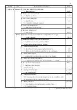
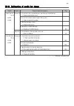
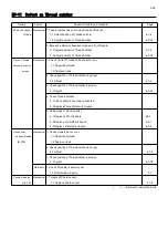
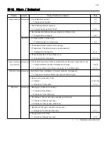
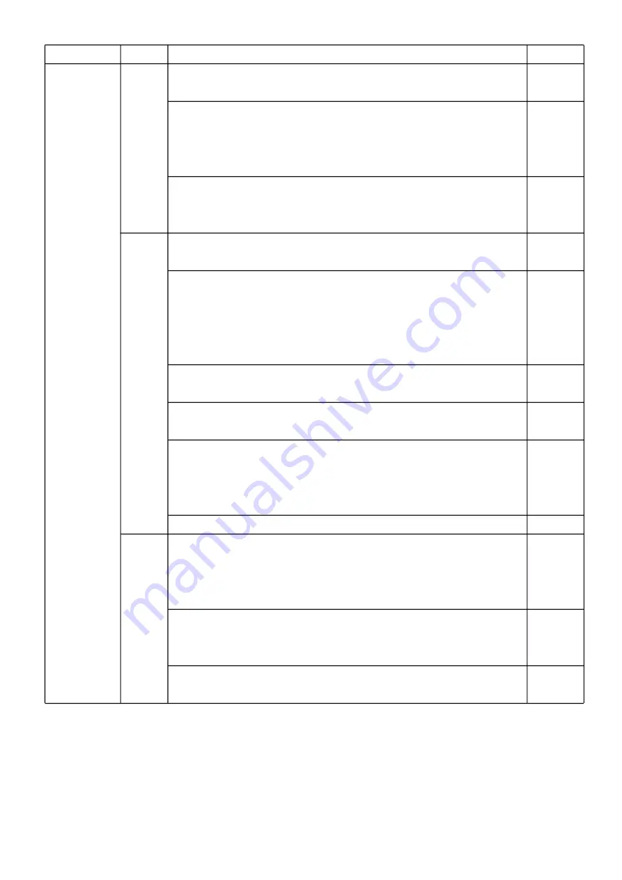
Trouble Factor Cause of trouble and measure
Page
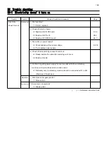
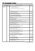
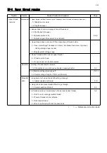
Thread break Operator 10. Is frame used to suit pattern size? ( 13-1 )
10-1 Use frame to suit pattern size.
11. When you dispose of thread (thread remains around rotary hook),
didn't you damage rotary hook, needle plate with scissors?
11-1 Tell to dispose of thread carefully.
11-2 Open needle plate to dispose of thread. ( 23-2 )
12. Didn't you neglect cleaning and oiling?
12-1 Tell to always clean and use cleanly. ( 23-2 )
12-2 Tell to oil regularly. ( 23-1b )2-7
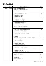
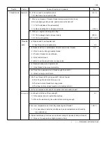
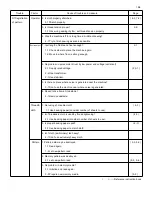
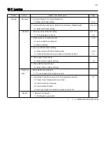
Thread & 1. Is thread used to suit needle size?
cloth 1-1 Use thread to suit needle size. 3-3
2. Is thread used to suit embroidery? (thread twist, tender thread). 3-2
2-1 Don't use too strongly twisted thread.
2-2 Twist of thread is to be left-wise.
2-3 Use tender thread.
2-4 Don't use thread with knot or uneven size.
3. Is thread properly wound aginst cone?
3-1 Use thread to be wound smoothly.
4. Isn't tip of cone warped or isn't thread caught in scratch?
4-1 Remove warp and scratch.
5. Don't use thread left for a long period? (inferior thread).
5-1 Don't buy thread more than you use.
5-2 Tell not to store thread for a long period.
5-3 Tell how to store. (direct sunshine. humidity dust etc.)
6. Isn't poor unwoven cloth used? Is number of sheets used proper?
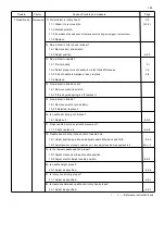
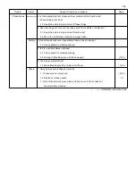
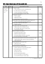
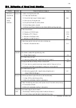
Environment
1. Is strength of table and floor enough?
2-1
1-1 Reconsider place to install the machine.
1-2 Move the machine to place where floor is strong enough.
2 Are room temperature and humidity proper against thread? ( 23-1 )
2-1 It is desirable to install air conditioner to keep temperature and humidity
in a certain level.
3. Doesn't embroidery machine receive direct sunlight? (cause of inferior thread)
3-1 See not to expose to sunlight (spread curtain)
( ) ----- Reference instruction book
Summary of Contents for HCR3-1502
Page 1: ... Maintenance Manual for Embroidery Machine HCR3E SERIES Version 1 2 HappyJapan Inc ...
Page 104: ...105 4 7 3 Adjustment of timing detecting unit 8 Finally put the cover back on ...
Page 107: ...107 ...
Page 172: ...172 E7 Electric system diagram E7 1 Pulse motor driver PMD wiring ...
Page 173: ...173 E7 2 Pulse motor driver PMD setup ...
Page 174: ...174 E7 3 Inverter wiring ...
Page 175: ...175 E7 4 Electrical connection diagram ...
Page 176: ...176 ...
Page 177: ...177 ...
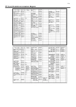
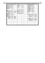
Page 178: ...178 E7 5 List of electrical connection diagram ...
Page 179: ...179 ...
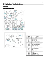
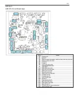
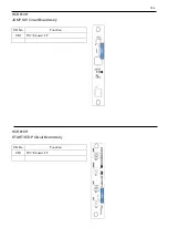
Page 180: ...180 E7 6 Explanation of function clrcuit board HCD8122 LCD CE MX Board Ass y ...
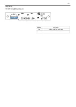
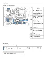
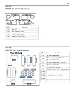
Page 181: ...181 HCD8116 TP SW Circuit Board Ass y CN No Function CN1 Switch output LED input ...

