background image

ADJUSTMENT MANUAL

5483

296-12-18 994/002
Justieranleitung  engl. 07.11

This Adjustment Manual is valid for machines 

from the following serial numbers onwards:

#  

2 492 189  

Summary of Contents for 5483 Series

Page 1: ...ADJUSTMENT MANUAL 5483 296 12 18 994 002 Justieranleitung engl 07 11 This Adjustment Manual is valid for machines from the following serial numbers onwards 2 492 189...

Page 2: ...n of PFAFF Service Manuals whether in whole or in part is only permitted with our previous authorization and with written reference to the source PFAFF Industriesysteme und Maschinen AG Hans Geiger St...

Page 3: ...dle clearance in sewing direction 19 1 05 13 Looper to needle clearance crosswise to sewing direction 20 1 05 14 Final adjustment of the needle height 21 1 05 15 Height of rear needle guard 22 1 05 16...

Page 4: ...37 1 05 31 Knee lever play 38 1 05 32 Knee lever stop 39 1 06 Adjusting the thread trimming device 900 71 40 1 06 01 Pre adjust the thread catcher 40 1 06 02 Positioning the ball stud 41 1 06 03 Posi...

Page 5: ...to be completely adjusted If only specific individual work steps are carried out both the preceding and following chapters must be observed Screws nuts indicated in brackets are fastenings for machin...

Page 6: ...equired postion Insert the adjustment pin into the appropriate adjustment hole and apply pressure Turn the balance wheel slightly backwards and forwards until the adjustment pin slips into the rear cr...

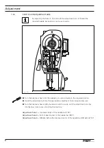
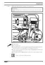
Page 7: ...h 911 the needle 6 must be centered in the needle hole in the sewing direction Loosen screws 1 2 3 and 4 Shift needle bar frame 5 according to the requirements Tighten screw 3 securely and slightly ti...

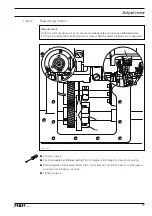
Page 8: ...Requirement With the needle bar at TDC pin in hole 1 the needle point must be positioned 11 mm above the needle plate or in the case of the H model 12 5 mm Bring the needle bar 1 to TDC Adjust needle...

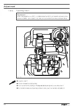
Page 9: ...Turn eccentric bush 2 screw 3 so that the marking faces downward and the surface of the eccentric bush 2 is at an angle of 45 to the front edge of the machine Loosen screw 4 and twist tension ring 5 a...

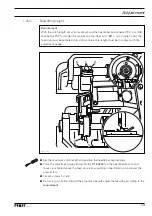
Page 10: ...rned Loosen screw 1 see Fig 1 03 Set stitch length at 0 Turn eccentric bush 2 screw 3 so that the marking faces downward and the surface of the eccentric bush 2 is at an angle of 45 to the front edge...

Page 11: ...m before TDC pin in hole 4 the feed dog must not move when the reverse feed switch is operated Loosen screw 1 Position needle bar 0 8 mm before TDC and adjust stitch length to maximum setting While op...

Page 12: ...odel machines and ma chines with 911 pin in hole 1 or 4 the slot of eccentric 2 must be pointing vertically Loosen screw 1 Position needle bar appropriately Twist eccentric 2 according to the requirem...

Page 13: ...lots and its entire length must be in contact with the adjustment gauge Set the maximum stitch length and position the needle bar appropriately Place the adjustment gauge Order No 61 111 642 19 on the...

Page 14: ...witch is fully pressed the stitch length must be 1 5 mm 2 When the maximum stitch length is set the feed dog must not come into contact with the needle plate cutout Set stitch length at 1 5 mm Turn sc...

Page 15: ...8 mm before TDC for H model machines and machi nes with 911 pin in hole 1 or 4 the slot in eccentric 2 must be positioned exactly un der the center of the shaft Loosen screw 1 Bring the needle bar in...

Page 16: ...e right hand side of the needle In this position attach C clamp order No 61 111 600 35 001 to the needle bar so that the upward motion of the needle bar is blocked Turn the balance wheel in the opposi...

Page 17: ...ooper 1 05 11 Looper height and looper angle Requirement When the looper holder 2 is in a vertical position 1 depending on the machine type there must be a clearance as indicated in the table below be...

Page 18: ...he required clearance is not obtained replace spacer 6 In order to do so looper 7 screw 8 has to be removed Place looper gauge 9 Order No 61 111 643 06 on the left edge of the cover plate sup port see...

Page 19: ...n the balance wheel until the looper point coming from the right reaches the left side of the needle Align looper unit 1 screw 2 according to the requirement If a clearance of 0 1 mm cannot be obtaine...

Page 20: ...the needle center of 3 2 mm By turning the balance wheel bring the looper 1 to its right point of reversal Place the 3 2 blade of looper gauge 2 Order No 61 111 643 06 against the needle 3 with its no...

Page 21: ...ches the left side of the needle the top edge of the needle eye must be 1 0 1 2 mm below the bottom edge of the looper Turn the balance wheel until the looper point which is coming from the right reac...

Page 22: ...ard Requirement When the needle bar is at bottom dead center pin in hole 3 the vertical surface of the needle guard 1 must cover about 2 3 of the needle eye Bring the needle bar to BDC Adjust needle g...

Page 23: ...right reaches the right side of the needle the needle guard 3 must still be in slight contact with the needle Turn the balance wheel until the looper point is located at the right side of the needle...

Page 24: ...e at the same height as the point of looper 1 By turning the balance wheel bring looper 1 to its left point of reversal Loosen screws 2 Adjust needle guard bracket 3 so that in this position the needl...

Page 25: ...g 1 18 1 05 18 Guard of looper avoiding motion eccentric Requirement During motion the eccentric 3 must not touch guard 1 Adjust guard 1 screws 2 accessible through adjustment holes according to the r...

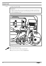
Page 26: ...and the needle bar frame 3 2 The take up lever 2 must be able to move freely in the center of the needle head slot and must not have any contact either at TDC or BDC By turning the handwheel make scr...

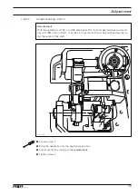
Page 27: ...he thread guide 2 must be vertical and attached with a screw in the center of the elongated hole Bring the needle bar to bottom dead center After loosening the screw adjust the needle thread regulator...

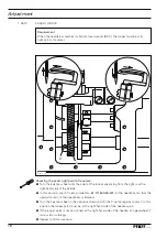
Page 28: ...cking mechanism only for machines with 911 Requirement The face side of the backtacking mechanism 1 must be in line with the bedplate surface of the machine Adjust backtacking mechanism 1 screws 2 and...

Page 29: ...the needle bar at bottom dead center pin in hole 3 the spreader link 3 must be at its rear point of reversal see arrow Bring the needle bar to bottom dead center Turn shaft 1 screws 2 according to the...

Page 30: ...cording to the re quirement by inserting an appropriate spacer 1 05 23 Spreader height only for machines with 911 Requirement When the tip of spreader 1 is above the looper there must be a clearance o...

Page 31: ...h the edge of the thread catcher cutout as seen in feed di rection Turn the balance wheel in sewing direction until the needle point is level with the back of the looper Loosen screws 1 and 2 Turn the...

Page 32: ...on with depressed reverse feed control and check the compliance with the requirement If required readjust the spreader settings 1 05 25 Functional sewing test only for machines with 911 Requirement As...

Page 33: ...plate edge guide must be 29 mm 2 The front edges of the thread take up device 3 and the thread regulator 1 must be about 8 mm apart Adjust thread regulator 1 screws 2 according to requirement 1 Adjust...

Page 34: ...1 are in the middle of the thread regulator 3 Depending on the type of material and thread used the basic setting may have to be modified 1 05 27 Looper thread puller Requirement With the needle bar...

Page 35: ...raised there must be a clearance of 7 mm between the pres ser foot and the needle plate Raise the presser bar lifter 1 Lift presser rod 2 and push the 7 mm thick blade of the adjustment gauge 3 Order...

Page 36: ...ment Turn screw 1 according to the requirement 1 05 29 Presser foot pressure Requirement The material feed should function perfectly at all times without any pressure marks occur ring on the fabric Fi...

Page 37: ...1 05 30 Knee lever rest position Requirement When in its rest position the knee lever connecting rod must be at right angles to the bedplate Raise the presser bar lifter Turn screw 1 nut 2 according...

Page 38: ...tightening crank 1 make sure that the knee lever shaft has no vertical play 1 05 31 Knee lever play Requirement When the presser foot is resting on the needle plate feed dog beneath the needle plate...

Page 39: ...ly operated 1 the presser foot must be lifted approx 7 mm or on H model machines approx 9 mm from the needle plate and 2 the presser bar lifter should drop by its own weight Raise the presser foot by...

Page 40: ...e guide plates 5 must be parallel to the mounting plate 1 3 The thread catcher 4 should move freely and with little play Fig 1 33 Remove mounting plate 1 screws 2 Loosen screws 3 Adjust thread catcher...

Page 41: ...ll stud 1 must 1 be located in the middle of actuator 5 and 2 have a clearance of 0 5 mm to the bottom of actuator 5 Fig 1 34 Set ball stud 1 in a vertical position Adjust bracket 2 screws 3 according...

Page 42: ...device is in a neutral position there must be a clearance of 7 mm between the point of the thread catcher 4 and the needle center Fig 1 35 Bring the thread trimming device into its neutral position T...

Page 43: ...there must be a clearance of 0 5 1 mm between the interlocking cam 2 and the roller 3 Fig 1 36 Loosen screws 1 so that the interlocking cam can be turned on its shaft with resistance Bring the needle...

Page 44: ...der is fully actuated there must be a clearance of about 0 5 mm between the top end of the elongated hole in plate 1 and the guide pin 3 Fig 1 37 Fully actuate the cylinder of the thread trimming devi...

Page 45: ...s are properly cut and bound Place material under the presser foot and sew a few stitches Remove cover plate 1 Position the needle as in Chapter 1 06 04Thread catcher interlock Operate the cutting cyl...

Page 46: ...ucer X2 1 Incremental transmitter adapter X2 2 Synchronizer adapter X2 3 Y5 911 backtacking device X3 Speed control unit X3 1 Y2 thread trimmer 900 X4 A2 Control panel BDF S3 X4 1 Y4 automatic foot li...

Page 47: ...47 2 02 Circuit diagrams 91 191 501 95 91 191 501 95 Part 1 Version 07 07 06 Circuit diagram...

Page 48: ...48 Circuit diagram Version 07 07 06 91 191 501 95 Part 2...

Page 49: ...49 91 191 501 95 Part 3 Version 07 07 06 Circuit diagram...

Page 50: ...und Maschinen AG is an authorized licensee of the PFAFF trademark PFAFF Industriesysteme und Maschinen AG Hans Geiger Str 12 IG Nord D 67661 Kaiserslautern Telefon 49 6301 3205 0 Telefax 49 6301 3205...

Reviews: