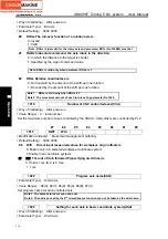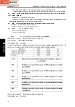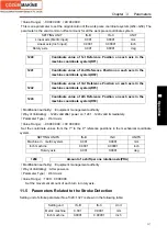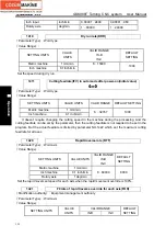
GSK988T Turning CNC system User Manual
320
Ⅱ
Operation
1324
Coordinate value of stored stroke check 3 in the positive direction
on each axis(PC3)
1325
Coordinate value of stored stroke check 3 in the negative direction
on each axis(NC3)
『
Modification authority
』
: Equipment management authority
『
Parameter Type
』
: Word axis
『
Default Setting
』
: No.1324 is 99 999 999, No.1325 is
-
99 999 999
『
Value Range
』
:
-
99 999 999
~
99 999 999
Respectively set the coordinate values of boundaries in positive and negative directions in the
mechanical coordinate system in each axis stroke detection 3 in memory type. Set inside of the
boundary as the restricted area to tools.
Note: The axis specified by the diameter must be set by the diameter value.
1326
Coordinate value
Ⅱ
of stored stroke check 1 in the positive
direction on each axis(PC12)
1327
Coordinate value
Ⅱ
of stored stroke check 1 in the negative
direction on each axis(NC12)
『
Modification authority
』
: Equipment management authority
『
Parameter Type
』
: Word axis
『
Default Setting
』
: NO.1326 is 99 999 999, NO.1327 is
-
99 999 999.
『
Value Range
』
:
-
99 999 999
~
99 999 999
Respectively set the positive and negative boundary coordinate values for each axis stroke
detection 1 in memory type in the machine coordinate system. Set outside of the boundary as the
restricted area. When parameter LMS (No.1300#2)is “1”, and the stroke limit switching signal EXLM
(G7.6) in memory type is “1”, the restricted area is valid, but it is invalid if it is set by No.1320 and
1321.
Note:
1. The axes programmed by the diameter must be set by the diameter value.
2. The parameter is invalid when parameter LMS (No.1320#2) is “0”, or the stroke limit
switching signal EXLM (G7.6) in the memory type is “0”. Then, the restricted area set by
parameter No.1320 or No. 1321 is valid.
11.6 Parameters Related to Feedrate
#7 #6 #5 #4 #3 #2 #1 #0
1401
RDR
TDR
RF0
RPD
『
Modification authority
』
: Equipment management authority
『
Default Setting
』:
0000 0000
#0 RPD
Manual rapid traverse during the period from power-on to completion of
Summary of Contents for 988T
Page 6: ...GSK988T Turning CNC System User Manual VI ...
Page 14: ...GSK988T Turning CNC System User Manual XIV ...
Page 15: ...Chapter 1 Programming Fundamentals 1 Ⅰ Programming Ⅰ PROGRAMMING ...
Page 16: ...GSK988T Turning CNC System User Manual 2 Ⅰ Programming ...
Page 194: ...GSK988T Turning CNC System User Manual 180 Ⅰ Programming ...
Page 195: ...Chapter Ⅰ Overview 181 Ⅱ Operation Ⅱ OPERATION ...
Page 196: ...GSK988T Turning CNC System User Manual 182 Ⅱ Operation ...
Page 217: ...Chapter Ⅲ Windows 203 Ⅱ Operation ...
Page 267: ...Chapter Ⅲ Windows 253 Ⅱ Operation Fig 3 51 Fig 3 52 ...


